Developing a new system architecture from scratch and validating its functional behavior is a time-consuming and complex task. Instead, an analogy-based design approach allows for the development of new systems derived from existing designs, reducing both development time and cost. This study presents the design and simulation of an aircraft hydraulic brake system using the LMS Amesim software tool. The simulation results demonstrate that the proposed brake system effectively meets aircraft hydraulic system design requirements, including MIL-H-5440H standards. The hydraulic pump achieved a stable system pressure of 209 bar, with peak pressure reaching 272 bar during high-demand conditions. The brake accumulator successfully charged to 100 bar within 6.5 seconds, storing 310 cc of oil and compressing 355 cc of nitrogen gas. The pressure reducing valve (PRV) effectively regulated system pressure from 210 bar to 100 bar for braking applications. The brake actuators responded within 0.75 seconds, delivering the required force to counteract wheel torque, while the shuttle valve successfully managed the transition between normal and emergency braking conditions. The return line maintained a stable backpressure of approximately 4 bar, preventing fluid surges. Overall, the simulation results validate the feasibility of the proposed hydraulic brake system, demonstrating compliance with military hydraulic standards and confirming its suitability for aircraft applications. Future improvements, such as antiskid integration, optimized flow control, and further system refinement, are discussed to enhance performance.
| Published in | Applied Engineering (Volume 9, Issue 1) |
| DOI | 10.11648/j.ae.20250901.12 |
| Page(s) | 9-36 |
| Creative Commons |
This is an Open Access article, distributed under the terms of the Creative Commons Attribution 4.0 International License (http://creativecommons.org/licenses/by/4.0/), which permits unrestricted use, distribution and reproduction in any medium or format, provided the original work is properly cited. |
| Copyright |
Copyright © The Author(s), 2025. Published by Science Publishing Group |
Aircraft Hydraulic Brake System, LMS, Hydraulic System Modeling, Brake System Architecture, MIL-H-5440H Compliance
Si No | Hydraulic Components in Circuit | Simulation Parameters |
|---|---|---|
1 | Hydraulic pump (EDP) | Rated rpm - 3000 psi |
2 | NRV in pump pressure line | Cracking Pressure-0.5 Bar, Flow rate – 20 lpm |
3 | High pressure relief valve | Cracking pressure - 3900 psi |
4 | Bootstrap reservoir | Volume – 4 liter capacity, HP Chamber pressure – 210 bar, LP chamber pressure – 3 to 5 bar |
5 | Low pressure relief valve (Overboard) | LP chamber cracking pressure – 5 bar |
6 | High pressure delivery filter | Flow coefficient – 75% |
7 | Pressure reducing valve | Inlet Pressure – 210 bar, Outlet Pressure – 100 bar, Flow rate – 20 lpm |
8 | NRV in emergency supply line | Cracking Pressure-0.5 Bar, Flow rate – 20 lpm |
9 | NRV in main supply line | Cracking Pressure-0.5 Bar, Flow rate – 20 lpm |
10 | Shuttle valve | Operating pressure – 100 bar |
11 | Wheel Brake accumulator | Pre charge pressure – 30 bar, Gas side medium – Nitrogen, Volume – 350 cc capacity |
12 | LH Brake control valve | Solenoid valve - normally closed 3 ways – 2 positions |
13 | RH Brake control valve | Solenoid valve - normally closed 3 ways – 2 positions |
14 | NRV in return line of LH Brake control valve | Cracking Pressure-0.5 Bar, Flow rate – 20 lpm |
15 | NRV in return line of RH Brake control valve | Cracking Pressure-0.5 Bar, Flow rate – 20 lpm |
16 | LH Brake unit | Brake system operating pressure – 100 bar, Wheel load – 9000 N-m |
17 | RH Brake unit | Brake system operating pressure – 100 bar, Wheel load – 9000 N-m |
Si No | Design Parameters for validation | Estimated design value | Reference standard | Simulated value from Amesim tool |
|---|---|---|---|---|
1 | Rated discharged pressure | Discharge pressure of 3000 psi ± 150 psi | MIL-P-19692E | Hydraulic system with rated pressure value of 3037 psi |
2 | Over pressure value | 3000 psi system = 3750 psi overpressure (for max limit of 3150 psi = 3937.5 psi) | MIL-P-19692E | |
3 | Maximum full flow pressure (developed at rated temperature, rated speed, and rated inlet pressure) | value shall be no less than 95 percent of rated discharged pressure (95% of 3150 psi = 2992.5 psi) | MIL-P-19692E | |
4 | Rated inlet pressure (at rated speed, maximum full-flow pressure, and rated temperature) | Design value of 2 ± 1 bar | By design estimate | 2.684 bar (39 psi) |
5 | Minimum inlet pressure (lowest inlet pressure at which the pump shall be required to operate during a system failure or during system flow transients) | Design value of 0 to 1 bar | By design estimate | 0 bar as per simulation (during pump start up, inlet pressure of 0 bar is maintained) |
6 | Maximum inlet pressure (maximum steady state inlet pressure at which the pump shall be required to operate in the hydraulic Systems) | Design value of 4 to 5 bar | By design estimate | 4.82 bar max. |
7 | Displacement (The displacement of the pump shall be the theoretical volume of the hydraulic fluid delivered in one revolution of its drive shaft in milliliters per revolution (ml/rev)) | Max. pump displacement of 100 ml/rev. for rated 3000 psi pressure | MIL-P-19692E | Max. displacement of 3.28 cc/rev at 2490 rated RPM (Figure 30) |
8 | Rated flow (The rated flow of the pump shall be the measured output of the pump under conditions of rated temperature, rated speed, rated inlet pressure and maximum full-flow pressure, using the hydraulic fluid) | Max. of 13 LPM | By design estimate | Max. rated flow of 8.13 LPM |
9 | Torque (The minimum performance requirements shall be stated as maximum input torque at rated flow and at rated discharge pressure) | Estimate about 10 to 15 N-m torque | By design estimate | |
10 | Inlet Pressure pulsations (Pressure pulsations are the oscillations of the inlet pressure, occurring during nominally steady operating conditions, at a frequency equal to or higher than the pump drive shaft speed) | pulsations shall not exceed ± 30 psi (2 bar to 6 bar) | By design estimate | Oscillations are within the 30 psi band limit (lower limit of 2.29 bar and higher limit of 4.02 bar) (Figure 33) |
11 | Outlet Pressure pulsations (Pressure pulsations are the oscillations of the discharge pressure, occurring during nominally steady operating conditions, at a frequency equal to or higher than the pump drive shaft speed) | pulsations shall not exceed ± 300 psi (182 bar to 238 bar) | MIL-P-19692E | Oscillations are within the 300 psi band limit (lower limit of 174.7 bar and higher limit of 227.7 bar) (Figure 32) |
12 | Response cycle time (The response time of the pump shall be the time interval between the instant when an increase (or decrease) in discharge pressure change initiates; and the subsequent instant when the discharge pressure reaches its first maximum (or minimum) value) | shall have a response time of 500 mille-seconds maximum | MIL-P-19692E | Effectively 200-250 mille-seconds during the service operations |
13 | Maximum transient pressure (The maximum transient pressure shall be the peak value of the oscillographic trace of discharge pressure, made during operation of a pump) | shall not exceed 135 percent of rated discharge pressure for systems (4050 psi max.) | MIL-P-19692E | |
14 | Maximum flow rate in PRV (The maximum flow rate across the pressure reducing valve during the LH/RH brake operation) | 7.5 LPM | By design estimate | In Simulation flow rate of about 7.31 LPM max. during brake operation (Figure 34) |
15 | Pressure fluctuation in PRV (Tolerance value for the Inlet and outlet pressure in the pressure reducing valve) | Inlet 210 ± 28 bar Outlet 100 ± 7 bar | By design estimate | Inlet pressure limit of 174.7 bar to 227.7 bar. |
16 | Flow demand in brake accumulator (The maximum flow rate demanded during the brake accumulator charging condition) | 8 LPM | By design estimate | 6 LPM during LH brake operation and 4.48 LPM during RH brake operation (Figures 25 and 26) |
17 | Storage Volume and pre-charge pressure in brake accumulator (The storage volume in oil and gas chamber and pre-charge pressure in the gas chamber of the brake accumulator to make the equilibrium condition during accumulator charging) | 350 cc volume capacity and pre-charge pressure of 30 bar in gas side chamber by design | By design estimate | Gas side of 355 cc and oil side of 310 cc with the precharge pressure in gas chamber of 30 bar (Figure 7) |
18 | Brake unit return line pressure (The pre-defined pressure at the return line during the brake operations) | Return line max pressure of 10 bar | By design estimate | |
19 | Flow requirement in brake unit (The maximum flow rate during the brake operating conditions at any brake LH/RH) | 8 LPM | By design estimate | 6.24 LPM during brake accumulator charging operation (Figure 8) |
20 | Storage Volume and pressure at the bootstrap reservoir (The storage volume and pressure at the HP and LP chamber of the bootstrap reservoir to make the inlet suction line to pump at pressurized condition all time) | LP Side of 3800 cc and HP side of 15 cc | By design estimate | LP Side max 3775 cc and HP side of 12 cc |
PRV | Pressure Reducing Valve |
EDP | Engine Driven Pump |
BCV | Brake Control Valve |
NRV | Non-Return Valve |
BMC | Brake Master Cylinder |
LH | Left-Hand (as in LH Brake) |
RH | Right-Hand (as in RH Brake) |
HP | High Pressure |
LP | Low Pressure |
MLG | Main Landing Gear |
MIL | Military (as in MIL-H-5440H, a military standard) |
psi | Pounds per Square Inch (Pressure Unit) |
lpm | Liters per Minute (Flow Rate Unit) |
Nm | Newton Meter (Torque Unit) |
Cq | Flow Coefficient |
UAV | Unmanned Aerial Vehicle |
Si No | Hydraulic system specification requirements according to MIL-H-5440H [19] |
|---|---|
1 | Aircraft hydraulic systems Class - Type II, Max. fluid operating temperature +135 Deg C Type - Class 3000 - 3000 psi nominal operating pressure |
2 | Fluid used. Conforming to MIL-H-83282 and MIL-H-5606 shall be used for hydraulic systems |
3 | Surge pressure. Peak pressure resulting from any phase of the system operation shall not exceed the percent value shown below for the main system, subsystem, or return system pressures Peak pressure – 135% of the operating pressure for class 3000 |
4 | Back pressure. The system shall be so designed that proper functioning of any unit such as internal actuator locks or brakes will not be affected by the maximum back pressure in the system. The system systems shall also be so designed that malfunctioning of any unit in the system will not render any other subsystem, emergency system, or alternate system inoperative because of back pressure. |
5 | Brakes. Back pressure resulting from the operation of any unit while the aircraft is on the ground shall create no greater back pressure at the brake valve return port than 90 percent of that pressure which will cause contact of braking surfaces. In addition, supply pressure to the brake system shall not drop below the maximum brake-operating pressure during the operation of any other subsystem in the aircraft during taxiing, landing, or takeoff |
6 | Pressure regulation. System pumps shall use an internal pressure regulating device to limit excessive pressure and to maintain constant pressure at varying flow demands. An independent safety relief valve shall also be incorporated into each system. |
7 | Hydraulic system design pressure characteristics Pump pressure at zero flow – 100% pump pressure Pump minimum pressure at full flow – 100%-100 psi |
8 | Subsystem isolation. Two or more subsystems pressurized by a common pressure source, one of which is essential to flight operation and the other not essential, shall be so isolated so that the system essential to flight operation will not be affected by any damage to the nonessential system. |
9 | Pump pulsation. For all power generating components (engine pumps, power packages, transfer units, etc), pump pulsations shall be controlled to a level which does not adversely affect the aircraft system tubing, components, and supports installation. |
10 | Utility system design. All hydraulically operated services that are essential to the accomplishment of the basic aircraft mission (weapon-bay doors, in-flight refueling, etc) or essential to land and stop the aircraft (landing gear, brakes, excluding types I and IV brakes of MIL-B-8584) shall have provisions for emergency actuation. No failure of the utility system shall result in loss of the aircraft or damage that would prevent safe flight and safe landing of the aircraft. |
11 | Wheel brake systems. Wheel brake systems shall be in accordance “with MIL-B-8584. |
12 | Hydraulic power failures. In aircraft, where direct mechanical control is unable to obtain aircraft-controllability and the emergency requirements of MIL-F-8785 cannot be accomplished following hydraulic power failures, an emergency power source shall be designed to provide controllability. Emergency system application. The means of engaging the emergency power system shall be either manual or automatic; however, they shall be of the simplest and most reliable nature possible, consistent with the requirements of the aircraft. |
13 | Fixed orifices. Orifices larger than 0.005 inch diameter but smaller than 0.070 inch diameter shall be protected by adjacent integral strainer elements (last chance screens) having screen-openings one-third to two-thirds of the diameter of the orifice being protected. Orifices smaller than the 0.005 inch diameter are prohibited. Multiple-orifice fixed restrictors are recommended as a means of increasing the orifice diameter and allowing the use of coarser strainer elements, minimizing the risk of clogging. Orifice and strainer elements, in combination, shall be strong enough to absorb system design flow and pressure drop without rupture or permanent deformation. |
14 | Hydraulic accumulators shall be in accordance with ARP 4553 (self-displacing hydraulic accumulators), or ARP 4378 (maintenance-free hydraulic accumulators). Gas requirements. Accumulators shall be charged with inert gas only. |
15 | Brake valves. Brake valves shall be installed in accordance with MIL-B-8584 and shall conform to MIL-V-5525. |
16 | Check valves. Check valves shall conform to MIL-V-25675, MIL-V-19067, or MIL-V-19069. |
17 | Directional control valves. The installation of directional control valves shall be compatible with the control valve performance such that the system operation may not be affected by back pressure, internal flow, or pressure surges which might tend to cause the valves to open or move from their setting or cause them to transfer fluid from one system to the other. Hydraulic control valves shall not be installed in the pilot’s cockpit or compartment. |
18 | Aircraft filters. All filters installed in the hydraulic system(s) shall be in accordance with the requirements of MIL-F-8815/4, MIL-F-8815/5,. and MIL-F-8815/6 as applicable. All filter elements shall be capable of maintaining the particulate contamination level equal to or better than the following: Class 8 per as 4059 in accordance with Method 3009 of FED-STD-791, with automatic particle counter calibrated per ARP 1192 or microscopic particle counts per ARP 598. |
19 | Reservoirs. Hydraulic reservoirs shall be designed in accordance with MIL-R-8931. When a hydraulic emergency system is used in any military aircraft, except trainer types, a separate emergency reservoir shall be provided. The emergency reservoir shall be located as remote as design permits from the main reservoir to minimize the effect of gunfire damage. Both the main and emergency reservoirs shall be serviceable through a common filler port unless design does not permit it. The fill and vent lines for all hydraulic reservoirs shall be designed so that rupture of any reservoir, fill, or vent lines will not cause fluid exchange between reservoirs or loss of sufficient fluid from any other reservoir to impair system operation. |
20 | Shuttle valves. Shuttle valves shall conform to MIL-V-5530 for Type I systems and MIL-V-19068 for Type II systems. Shuttle valves shall not be used in installations in which a force balance can be obtained on both inlet ports simultaneously which may cause the shuttle valve to restrict flow from the outlet port. Where shuttle valves are necessary to connect an actuating cylinder with the normal and emergency systems.. |
21 | Pump suction line design. The pump suction line shall be designed to provide flow and pressure at the pump inlet port. This requirement shall include operating the pump at the maximum output flow and shall include all ground and flight conditions the aircraft will encounter. Zero g and negative g conditions and low temperature start and operation shall also be included in the above requirement. Pressure and flow rates versus time for each mission profile along with the power load analysis. Type of power-driven pump and displacement, Including flow rate curve showing engine and pump rpm, for all phases of flight such as takeoff, climb, cruise, and landing. |
| [1] | Hunt, T., Vaughan, N. Hydraulic Handbook, 9th edn, Elsevier, 1996. |
| [2] | Moir, I., Seabridge, A. Aircraft Systems: Mechanical, Electrical, and Avionics Subsystems Integration, vol. 2, Professional Engineering Publishing, Bury St Edmunds, 2001, pp. 91–124. |
| [3] | Wahi, M. K., Warren, S. M., Straub, H. H. An Extended Prediction Model for Airplane Braking Distance and a Specification for a Total Braking Prediction System, vol. I, Ohio, 1977. (ASD-TR-77-6 Vol. I). |
| [4] | Wahi, M. K., Warren, S. M., Straub, H. H. An Extended Prediction Model for Airplane Braking Distance and a Specification for a Total Braking Prediction System, vol. II, Ohio, 1977. (ASD-TR-77-6 Vol. II). |
| [5] | Bailey, D. A. Investigation of Improvements in Aircraft Braking Design. Thesis (Doctor of Philosophy), Cranfield University, Cranfield, 2004. |
| [6] | LMS. AMESim Help, AMEHelp, 2013. |
| [7] | Neto, M. M., Goes, L. C. S. Use of LMS Amesim® Model and a Bond Graph Support to Predict Behavior Impacts of Typical Failures in an Aircraft Hydraulic Brake System. Journal of the Brazilian Society of Mechanical Sciences and Engineering, 2018, 40(9). |
| [8] | Tao, L. Design Analysis and Optimization for the Civil Aircraft Hydraulic Supply System Based on AMESim. IEEE/CSAA International Conference on Aircraft Utility Systems, 2016, pp. 890–894. |
| [9] | Wang, H. X., Shang, Y. X., Jia, J. H., Jiao, Z. X. Simulation and Analysis for Users' Flow Requirements of Aircraft Hydraulic System Based on AMESim. IEEE/CSAA International Conference on Aircraft Utility Systems, 2016, pp. 814–819. |
| [10] | Zhao, J., Hu, Z., Zhu, B., Gong, J. Integrated Model Control of Brake–Wheel System Using Bond Graph Method. Advances in Mechanical Engineering, 2018, 10(7), 1–16. |
| [11] | Castro, R., Morona, Y. M., Machado, K., Cavaler, L. C., Rocha, A. D. S. Experimental Analysis of the Supply Pressure Variation of the Hydraulic System. International Journal of Recent Contributions from Engineering, Science & IT (iJES), 2014, 2(4), 28. |
| [12] | Liu, J., Guo, L., Ma, J., Ge, Y., Wu, J., Ma, Z. Design and Simulation of Hydraulic Braking System for Loader Based on AMESim. Advanced Manufacturing and Automation IX. IWAMA 2019, Lecture Notes in Electrical Engineering, vol. 634, Springer, Singapore, 2020. |
| [13] | Tao, L. Design Analysis and Optimization for the Civil Aircraft Hydraulic Supply System Based on AMESim. 2016 IEEE International Conference on Aircraft Utility Systems (AUS), Beijing, 2016, pp. 890-894. |
| [14] | Chen, J., Liu, X., Wang, T., et al. Charging Valve of the Full Hydraulic Braking System. Advances in Mechanical Engineering, 2016. |
| [15] | FAA. Hydraulic System Certification Tests and Analysis, FAA AC 25.1435-1, 2001 Edition, May 21, 2001. |
| [16] | Joshi, A., Jayan, P. Modeling and Simulation of Aircraft Hydraulic System. AIAA Modeling and Simulation Technologies Conference and Exhibit, 2002. |
| [17] | Yang, I., Lee, W., Hwang, I. A Model-Based Design Analysis of Hydraulic Braking System. SAE Technical Paper, 2003-01-0253, 2003. |
| [18] | Li, J., Zhang, X., Yin, Y., Zhang, J. Dynamic Temperature Simulation of an Accumulator in Aircraft Hydraulic Systems. Proceedings of 2011 International Conference on Fluid Power and Mechatronics, 2011. |
| [19] | Military Standard. Design and Installation Requirements for Aircraft Hydraulic Systems, MIL-H-5440H, 1993. |
| [20] | Military Standard. General Specification for Variable Flow Hydraulic Pumps, MIL-P-19692E, 1994. |
| [21] | Military Standard. Performance Specification: Hydraulic Fluid, Petroleum Base: Aircraft, Missile, and Ordnance, MIL-PRF-5606H, 2002. |
| [22] | Poole, K., Thielecke, F., Maediger, C. Model-Based Development of Health Monitoring Functions for Aircraft Hydraulic Systems. Proceedings of the ASME/BATH Symposium on Fluid Power and Motion Control, 2013. |
APA Style
Karunanidhi, K., Manoharan, M., Rajamanickam, S. K. (2025). An Aircraft Hydraulic Brake System Model Analysis Using LMS Amesim Tool. Applied Engineering, 9(1), 9-36. https://doi.org/10.11648/j.ae.20250901.12
ACS Style
Karunanidhi, K.; Manoharan, M.; Rajamanickam, S. K. An Aircraft Hydraulic Brake System Model Analysis Using LMS Amesim Tool. Appl. Eng. 2025, 9(1), 9-36. doi: 10.11648/j.ae.20250901.12
@article{10.11648/j.ae.20250901.12,
  author = {Karthik Karunanidhi and Mohanraj Manoharan and Sathish Kumar Rajamanickam},
  title = {An Aircraft Hydraulic Brake System Model Analysis Using LMS Amesim Tool},
  journal = {Applied Engineering},
  volume = {9},
  number = {1},
  pages = {9-36},
  doi = {10.11648/j.ae.20250901.12},
  url = {https://doi.org/10.11648/j.ae.20250901.12},
  eprint = {https://article.sciencepublishinggroup.com/pdf/10.11648.j.ae.20250901.12},
  abstract = {Developing a new system architecture from scratch and validating its functional behavior is a time-consuming and complex task. Instead, an analogy-based design approach allows for the development of new systems derived from existing designs, reducing both development time and cost. This study presents the design and simulation of an aircraft hydraulic brake system using the LMS Amesim software tool. The simulation results demonstrate that the proposed brake system effectively meets aircraft hydraulic system design requirements, including MIL-H-5440H standards. The hydraulic pump achieved a stable system pressure of 209 bar, with peak pressure reaching 272 bar during high-demand conditions. The brake accumulator successfully charged to 100 bar within 6.5 seconds, storing 310 cc of oil and compressing 355 cc of nitrogen gas. The pressure reducing valve (PRV) effectively regulated system pressure from 210 bar to 100 bar for braking applications. The brake actuators responded within 0.75 seconds, delivering the required force to counteract wheel torque, while the shuttle valve successfully managed the transition between normal and emergency braking conditions. The return line maintained a stable backpressure of approximately 4 bar, preventing fluid surges. Overall, the simulation results validate the feasibility of the proposed hydraulic brake system, demonstrating compliance with military hydraulic standards and confirming its suitability for aircraft applications. Future improvements, such as antiskid integration, optimized flow control, and further system refinement, are discussed to enhance performance.},
 year = {2025}
}
TY  - JOUR
T1  - An Aircraft Hydraulic Brake System Model Analysis Using LMS Amesim Tool
AU  - Karthik Karunanidhi
AU  - Mohanraj Manoharan
AU  - Sathish Kumar Rajamanickam
Y1  - 2025/03/28
PY  - 2025
N1  - https://doi.org/10.11648/j.ae.20250901.12
DO  - 10.11648/j.ae.20250901.12
T2  - Applied Engineering
JF  - Applied Engineering
JO  - Applied Engineering
SP  - 9
EP  - 36
PB  - Science Publishing Group
SN  - 2994-7456
UR  - https://doi.org/10.11648/j.ae.20250901.12
AB  - Developing a new system architecture from scratch and validating its functional behavior is a time-consuming and complex task. Instead, an analogy-based design approach allows for the development of new systems derived from existing designs, reducing both development time and cost. This study presents the design and simulation of an aircraft hydraulic brake system using the LMS Amesim software tool. The simulation results demonstrate that the proposed brake system effectively meets aircraft hydraulic system design requirements, including MIL-H-5440H standards. The hydraulic pump achieved a stable system pressure of 209 bar, with peak pressure reaching 272 bar during high-demand conditions. The brake accumulator successfully charged to 100 bar within 6.5 seconds, storing 310 cc of oil and compressing 355 cc of nitrogen gas. The pressure reducing valve (PRV) effectively regulated system pressure from 210 bar to 100 bar for braking applications. The brake actuators responded within 0.75 seconds, delivering the required force to counteract wheel torque, while the shuttle valve successfully managed the transition between normal and emergency braking conditions. The return line maintained a stable backpressure of approximately 4 bar, preventing fluid surges. Overall, the simulation results validate the feasibility of the proposed hydraulic brake system, demonstrating compliance with military hydraulic standards and confirming its suitability for aircraft applications. Future improvements, such as antiskid integration, optimized flow control, and further system refinement, are discussed to enhance performance.
VL  - 9
IS  - 1
ER  -
Department of Mechanical Engineering, Government College of Engineering Salem, Salem, India
Department of Mechanical Engineering, Government College of Engineering Salem, Salem, India
Department of Automobile Engineering, Hindustan Institute of Technology and Science, Chennai, India
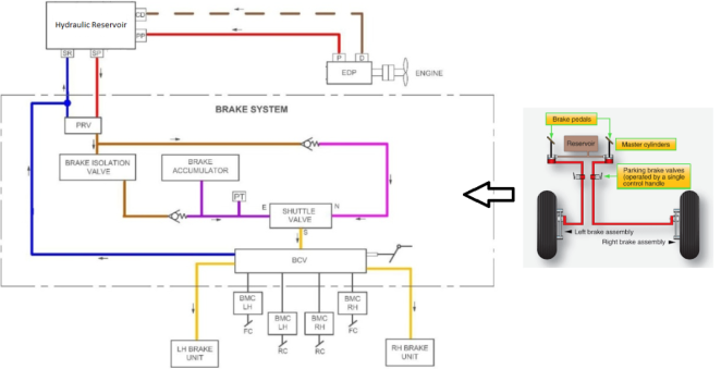
Figure 1. The Proposed hydraulic brake system.
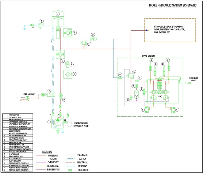
Figure 2. Brake system architecture for aircraft application.
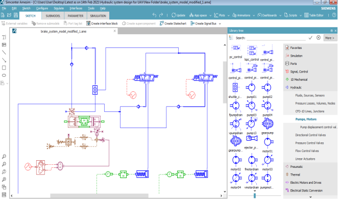
Figure 3. LMS Amesim model environment for modeling Hydraulic brake system.
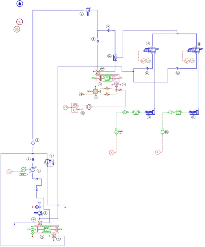
Figure 4. Amesim model for Hydraulic brake system schematic.
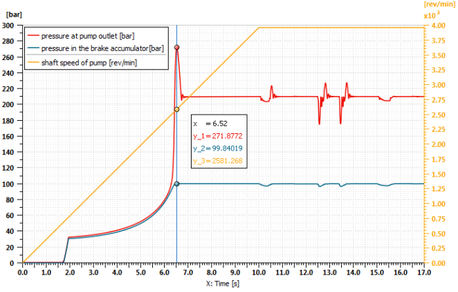
Figure 5. Overall Pump performance curve.
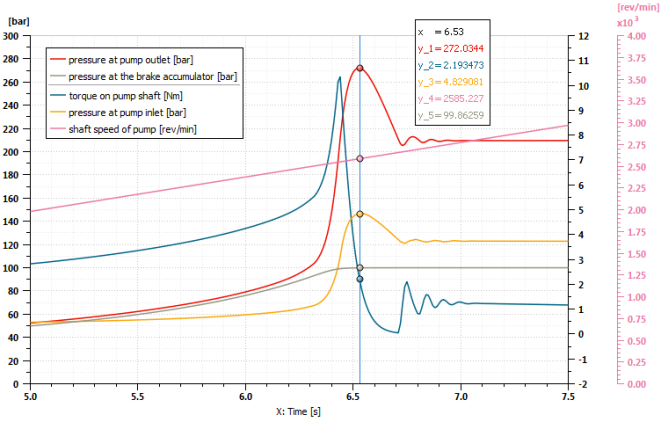
Figure 6. Pump characteristics during peak pump pressure.
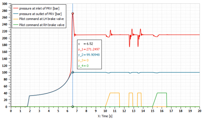
Figure 7. Pressure reducing valve characteristics during Pilot command.
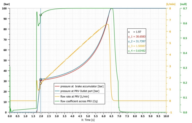
Figure 8. PRV characteristics during brake accumulator charging.
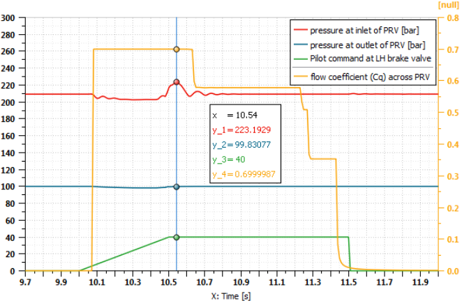
Figure 9. PRV characteristics during LH brake application.
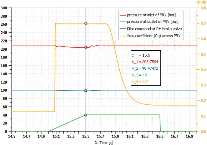
Figure 10. PRV characteristics during RH brake application.
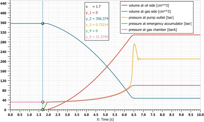
Figure 11. Volume variation in Oil & Gas side during brake accumulator charging.
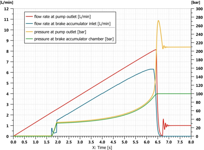
Figure 12. Flow rate correlation between pump outlet and brake accumulator during emergency charging.
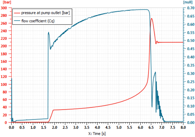
Figure 13. Flow coefficient (Cq) across Pump HP filter during Brake accumulator charging.
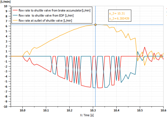
Figure 14. Flow rate at shuttle valve inlet and outlet during LH brake command from pilot.
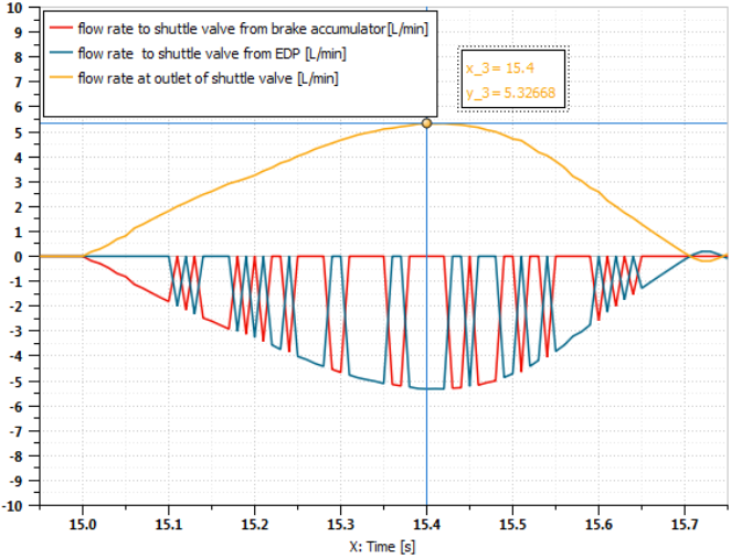
Figure 15. Flow rate at shuttle valve inlet and outlet during RH brake command from pilot.
Figure 16. Flow rate correlation in BCV, brake accumulator & Pump inlet during LH brake command from pilot.
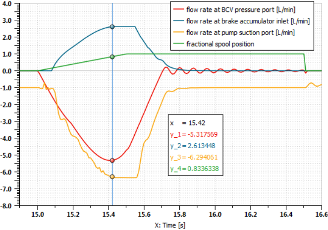
Figure 17. Flow rate correlation in BCV, brake accumulator & Pump inlet during RH brake command from pilot.
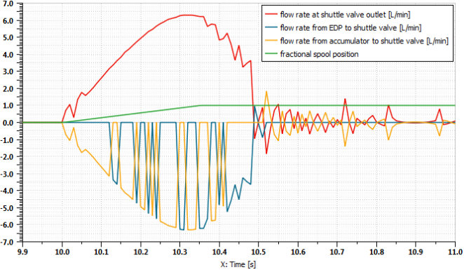
Figure 18. Flow fluctuations in the shuttle valve during LH brake command from pilot.
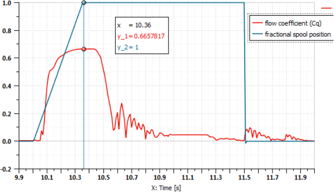
Figure 19. Flow coefficient (Cq) across Pump HP filter during LH Brake application.
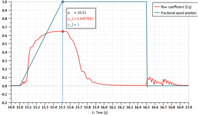
Figure 20. Flow coefficient (Cq) across Pump HP filter during RH Brake application.
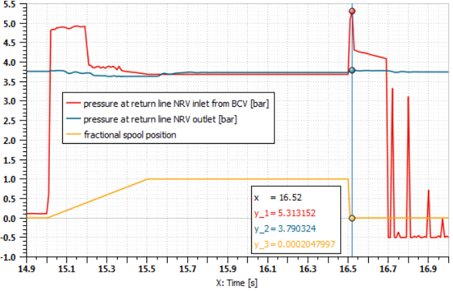
Figure 21. Brake return line (RH) behavior along with BCV spool movement.
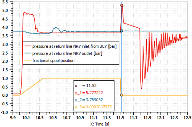
Figure 22. Brake return line (LH) behavior along with BCV spool movement.
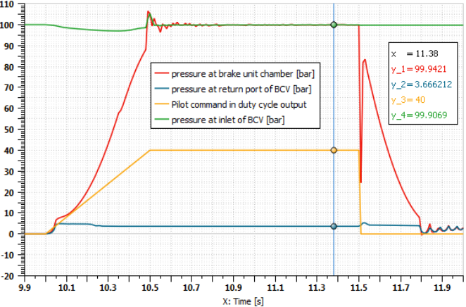
Figure 23. LH Brake unit performance behavior with pilot command.
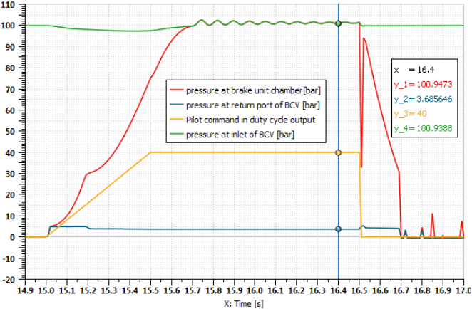
Figure 24. RH Brake unit performance behavior with pilot command.
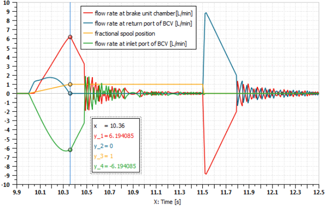
Figure 25. LH Brake unit flow rate behavior with pilot command.
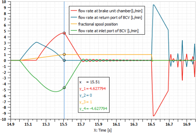
Figure 26. RH Brake unit flow rate behavior with pilot command.
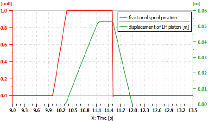
Figure 27. LH Brake unit displacement rate behavior with pilot command.
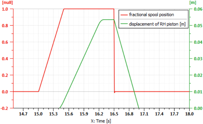
Figure 28. RH Brake unit displacement rate behavior with pilot command.
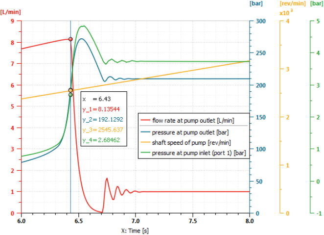
Figure 29. Pump Performance curve.
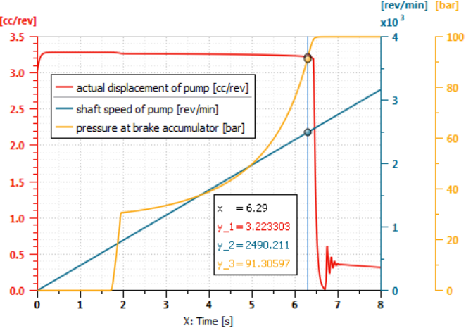
Figure 30. Pump displacement curve.
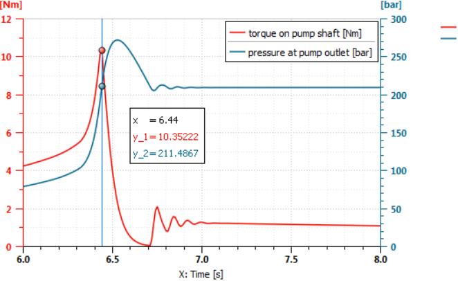
Figure 31. Pump Torque curve.
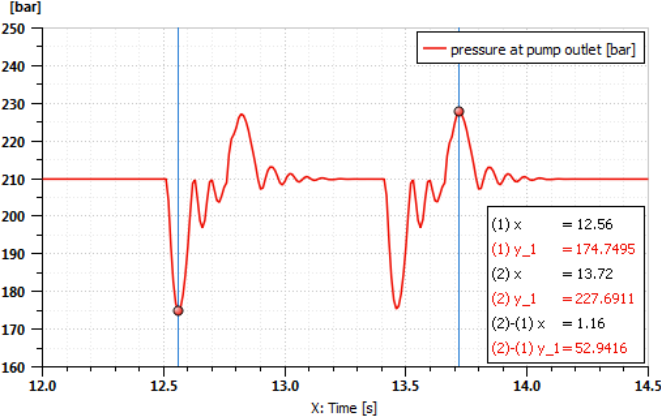
Figure 32. Outlet Pump Pulsation curve.
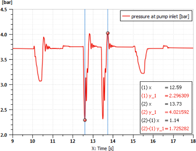
Figure 33. Inlet Pump Pulsation curve.
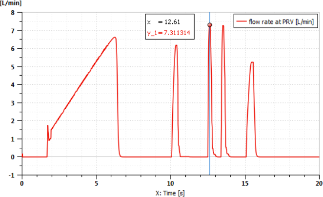
Figure 34. Flow rate in Pressure reducing valve (PRV).
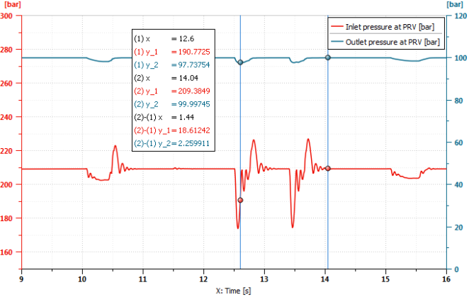
Figure 35. Pressure pulsation in Pressure reducing valve (PRV).
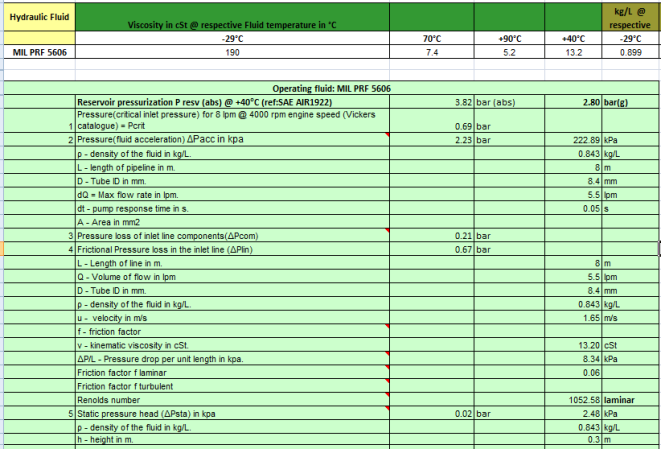
Figure 36. Hydraulic sizing calculation sample sheet during design.
Information