Research Article | | Peer-Reviewed

Effects of Masonry Infills on the Lateral Stiffness of Reinforced Concrete Buildings

Received: 2 March 2025     Accepted: 18 March 2025     Published: 31 March 2025
Views:       Downloads:
Abstract

Block infills are usually regarded as non-loadbearing components in buildings, and are frequently neglected in the analysis and design of building structures. The main objective of this study is to perform static nonlinear analysis of hollow concrete block (HCB) infilled reinforced concrete buildings (RC) subjected to a seismic excitation. For this study, three different buildings were selected as case studies: a seven-story, an eleven-story, and a sixteen-story building, each with a standard floor plan. Bare RC frame buildings were analyzed and designed on ETABS based on Ethiopian Buildings Code Standards (ES EN: 2015). While numerical modeling and static pushover analysis of the designed building model cases were computed using SeismoStruct. The masonry panel model was employed to reproduce the behaviour of the full-scale infilled frame model using diagonal compression struts. The results from the pushover analysis were used to determine the fundamental vibration period and generate the capacity curves. It was observed that the presence of infills had a highly significant impact, causing a considerable increase in base shear until the infills began to crack. Additionally, the infills played a major role in reducing the fundamental vibration period of the structures. A seismic base shear of 5,150kN was found at significant damage performance levels with the corresponding roof displacements of 300, 420, and 600mm for seven-story, eleven-story and sixteen-story building models respectively. While their respective on set cracks of infills were observed at 17mm, 20mm and 24mm roof displacement. Therefore, for relatively high-rise buildings, the contribution of infills in terms of stiffness and energy dissipation becomes more important, as their impact on base shear and fundamental period is both substantial and significant.

Published in American Journal of Civil Engineering (Volume 13, Issue 2)
DOI 10.11648/j.ajce.20251302.12
Page(s) 68-80
Creative Commons

This is an Open Access article, distributed under the terms of the Creative Commons Attribution 4.0 International License (http://creativecommons.org/licenses/by/4.0/), which permits unrestricted use, distribution and reproduction in any medium or format, provided the original work is properly cited.

Copyright

Copyright © The Author(s), 2025. Published by Science Publishing Group

Keywords

Bare Frame, Infilled Model, Fundamental Period, Pushover Analysis, Capacity Curve

1. Introduction
HCBs are commonly used as infill walls in building constructions and are among the frequently utilized masonry infills. These infills plays a role in the lateral response of the building, there by affecting their lateral stiffness . Although the effects of interaction between infill walls and frames against seismic excitation are considerable, most studies have overlooked to integrate into frame system for overall performance of RC structure . These infills contribute to the lateral behavior of buildings, which in turn affects their lateral stiffness, energy dissipation mechanism, natural periods, and mode shapes. Traditional design methods typically takes masonry infills as imposed loads on the floor and corresponding beams thereby underrating their effects on the lateral stiffness. According to Euro code 8 (1998-1) (par. 4.3.6.1), if infill walls are in contact with the frame but are not structurally connected to it (such as through ties, belts, posts, or shear connectors), they can be classified as "non-structural elements" . This classification permits the neglect of their stiffness and strength in structural analysis. Therefore, it is essential to model the infill walls alongside the frame elements to accurately account for the contribution of masonry infills to the building's overall lateral stiffness. The fundamental vibration period of a building is influenced by the distribution of its stiffness and mass along its height. As a result, any element that contributes to rigidity, mass, or both will impact the building's fundamental period. Presence of infill walls reduced the fundamental period of the building by 5-10% compared to bare frame buildings with or without shear walls .
Tasnimi and Mohenkhan studied the effect of presence of infill walls on the seismic demands of the RC structures using equivalent strut models. The study indicated that presence of infill walls in a story leads to reducing the relative displacement and increasing base shear forces. Rajesh et al. studied the performance of RC frames with and without infills by modeling the infills as equivalent diagonal struts. The results indicated that a decrease in the time period leads to an increase in the building's base shear. Additionally, the total weight of the building is lower in the strut model compared to the bare-frame model. The unexpected response of structural systems with integrated infill panels during strong earthquakes is attributed to the failure to account for the significant interaction between the infill walls and the building frames. Various techniques have been proposed in the literature for simulating infilled frames, which can generally be categorized into two groups: micro-models and simplified macro-models.
The micro-model is a technique in which the infill panel is divided into discrete elements, enabling a more accurate and detailed level of analysis. These models assist in analyzing crack patterns, crack progression at different failure stages, and bonding characteristics under various loading conditions. In contrast, macro models focus on larger-scale modeling of building structures, allowing for the study of the overall behavior of infills and primary structural elements under lateral loading. .
Macro-modeling is employed to accurately represent the response of infill walls, using equivalent diagonal struts to model how the infill walls contribute to the overall response of the infilled frame. The equivalent diagonal compression strut method has emerged as the most widely used approach for analyzing infilled frame systems. Infill walls act as equivalent diagonal compression struts in resisting lateral loads, rather than functioning as a homogeneous shear wall. The stresses are transferred from the frame to the infill wall through a compression zone . This method replaces the infill panel by two diagonal, compression-only struts. This approach is advantageous since the masonry is a very heterogeneous material and it is hard to predict the material properties of the constituent members accurately.
The focus of this research is to investigate the effect of HCB masonry infills in RC buildings subjected to seismic excitations. Pushover analysis is performed to capture the maximum story displacements and dominant time periods of the building. Numerical analysis is performed on seven-story, eleven-story and sixteen-story buildings, each consisting of a bare frame and featuring distinct percentages of infill configurations. RC frame buildings without infills are analyzed and designed using ETABS . The analysis and design of the proposed building models are carried out following the conventional design approach outlined in the latest Ethiopian Building Code Standards ES EN 1991: 2015 , ES EN 1992: 2015 and ES EN 1998: 2015 . While numerical modeling and static pushover analysis of the designed building model cases with the proposed infill configurations are computed using SeismoStruct . The masonry panel model is represented by using diagonal compression struts.
2. Methodology
2.1. General Background
The study followed a three-step approach: first, the conventional design of building models; second, the determination of infill wall parameters; and third, the numerical modeling and analysis of building cases using Seismostruct. The capacity design of the buildings helps determine appropriate structural member sections, providing a clear focus on the influence of infill walls under lateral loading. The mechanical properties of the infill walls were identified and utilized as input data for the analysis software. For this study, three building model cases having typical floor plans and architectural layouts with varying percentage of infill configuration were studied. Seven-story, eleven-story and sixteen-story buildings were studied as both frame without infill and as infilled building model cases with 25%, 50%, 75% and 100% infills.
2.2. Conventional Design of Building Models
First, the structural member demands for the building cases were determined using ETABS software. This process delivered the precise dimensions of the structural components along with the required reinforcement specifications. During the analysis stage, the effect of masonry walls was only considered as imposed loads on the building, following the conventional design approach. The response spectrum method was employed for seismic load analysis, with seismic zone III taken into account for the building's location. Table 1 to Table 6 present the design results for the seven-story, eleven-story and sixteen-story building models, summarizing design results for beam and column cross-sections along with their reinforcement demands.
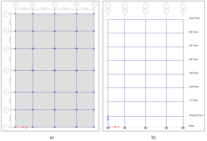
Figure 1. a) Typical floor plan b) typical elevation plan for seven-story building.
Table 1. Beam reinforcement details for seven-story building.

Beam

Story

Grid

Cross section

Longitudinal bar

Stirrup

Support

Span

Bottom

Top

Bottom

Top

Ground Floor

A-E

400mm x 250mm

3Ø14

3Ø14

3Ø14

2Ø14

Ø8@200mm

1-7

400mm x 250mm

3Ø14

3Ø14

3Ø14

2Ø14

Ø8@200mm

1st Floor

A&E

400mm x 250mm

2Ø16+1Ø14

3Ø16

2Ø16+1Ø14

2Ø16

Ø10@160mm

B&D

400mm x 250mm

2Ø16+2Ø14

4Ø16

2Ø16+2Ø14

2Ø16

Ø10@160mm

C

400mm x 250mm

3Ø16

2Ø16+2Ø14

3Ø16

2Ø16

Ø10@160mm

1-7

400mm x 250mm

2Ø16+2Ø14

4Ø16

2Ø16+2Ø14

2Ø16

Ø10@160mm

2nd-6th Floor

1,7,A&E

400mm x 250mm

2Ø16+1Ø14

3Ø16

2Ø16+1Ø14

2Ø16

Ø10@160mm

C,2&6

400mm x 250mm

2Ø16+2Ø14

4Ø16

2Ø16+2Ø14

2Ø16

Ø10@160mm

3&5

400mm x 250mm

4Ø16

2Ø16+2Ø14

4Ø16

2Ø16

Ø10@160mm

4,B&D

400mm x 250mm

2Ø16+2Ø14

5Ø16

2Ø16+2Ø14

2Ø16

Ø10@160mm

Roof Floor

1,7,A&E

400mm x 250mm

3Ø14

3Ø14

3Ø14

2Ø14

Ø10@160mm

2,3,5&7

400mm x 250mm

2Ø16+1Ø14

2Ø16+1Ø14

2Ø16+1Ø14

2Ø16

Ø10@160mm

4,B,C&D

400mm x 250mm

3Ø16

3Ø16

3Ø16

2Ø16

Ø10@160mm

4,B&D

400mm x 250mm

2Ø16+2Ø14

5Ø16

2Ø16+2Ø14

2Ø16

Ø10@160mm

Table 2. Column reinforcement details for seven-story building.

Column

Story

Column Types

Cross section

Longitudinal bar

Stirrup

Basement and Ground

C-1

600mm x 300mm

10Ø16

4-leg Ø10@180mm

C-2

600mm x 400mm

12Ø16

4-leg Ø10@180mm

C-3

500mm x 500mm

10Ø20

4-leg Ø10@180mm

1st and 2nd

C-1

500mm x 300mm

8Ø16

4-leg Ø10@180mm

C-2

500mm x 400mm

10Ø16

4-leg Ø10@180mm

C-3

500mm x 400mm

10Ø16

4-leg Ø10@180mm

3rd and 4th

C-1

400mm x 300mm

6Ø16

3-leg Ø10@180mm

C-2

500mm x 300mm

8Ø16

4-leg Ø10@180mm

C-3

500mm x 300mm

8Ø16

4-leg Ø10@180mm

4th and 6th

C-1

300mm x 300mm

6Ø14

2-leg Ø10@180mm

C-2

400mm x 250mm

6Ø16

3-leg Ø10@180mm

C-3

400mm x 250mm

8Ø16

4-leg Ø10@180mm

Table 3. Beam reinforcement details for eleven-story building.

Beam

Story

Grid

Cross section

Longitudinal bar

Stirrup

Support

Span

Bottom

Top

Bottom

Top

Ground Floor

A-E

400mm x 250mm

3Ø14

3Ø14

3Ø14

2Ø14

Ø8@200mm

1-7

400mm x 250mm

3Ø14

3Ø14

3Ø14

2Ø14

Ø8@200mm

First Floor

1,7,A&E

400mm x 250mm

3Ø14

2Ø16+1Ø14

3Ø14

2Ø16

Ø10@160mm

B&D

400mm x 250mm

2Ø16+2Ø14

4Ø16

2Ø16+2Ø14

2Ø16

Ø10@160mm

C

400mm x 250mm

3Ø16

2Ø16+2Ø14

3Ø16

2Ø16

Ø10@160mm

2,4&6

400mm x 250mm

2Ø16+2Ø14

2Ø16+2Ø14

2Ø16+2Ø14

2Ø16

Ø10@160mm

3&5

400mm x 250mm

3Ø16

3Ø16

3Ø16

2Ø16

Ø10@160mm

2nd-10th Floor

1,7,A&E

400mm x 250mm

3Ø14

3Ø16

3Ø14

2Ø16

Ø10@160mm

2&6

400mm x 250mm

2Ø16+2Ø14

2Ø16+3Ø14

2Ø16+2Ø14

2Ø16

Ø10@160mm

3&5

400mm x 250mm

3Ø16

2Ø16+2Ø14

3Ø16

2Ø16

Ø10@160mm

C

400mm x 250mm

3Ø16

4Ø16

3Ø16

2Ø16

Ø10@160mm

4,B&D

400mm x 250mm

2Ø16+2Ø14

5Ø16

2Ø16+2Ø14

2Ø16

Ø10@160mm

Roof Floor

1,7,A&E

400mm x 250mm

3Ø14

3Ø14

3Ø14

2Ø14

Ø10@160mm

2,3,5&6

400mm x 250mm

2Ø16+1Ø14

2Ø16+1Ø14

2Ø16+1Ø14

2Ø16

Ø10@160mm

4

400mm x 250mm

3Ø16

3Ø16

3Ø16

2Ø16

Ø10@160mm

B,C&D

400mm x 250mm

2Ø16+1Ø14

3Ø16

2Ø16+1Ø14

3Ø16

Ø10@160mm

Table 4. Column reinforcement details for eleven-story building.

Column

Story

Column Types

Cross section

Longitudinal bar

Stirrup

Basement and Ground

C-1

600mm x 400mm

12Ø16

4-leg Ø10@180mm

C-2

700mm x 500mm

14Ø20

7-leg Ø10@180mm

C-3

800mm x 500mm

14Ø20

7-leg Ø10@180mm

1st and 2nd

C-1

500mm x 400mm

10Ø16

4-leg Ø10@180mm

C-2

600mm x 500mm

12Ø20

6-leg Ø10@180mm

C-3

700mm x 500mm

12Ø20

6-leg Ø10@180mm

3rd and 4th

C-1

500mm x 400mm

10Ø16

4-leg Ø10@180mm

C-2

600mm x 400mm

10Ø20

4-leg Ø10@180mm

C-3

600mm x 500mm

10Ø20

5-leg Ø10@180mm

5th and 6th

C-1

500mm x 300mm

8Ø16

4-leg Ø10@180mm

C-2

500mm x 400mm

10Ø16

4-leg Ø10@180mm

C-3

600mm x 400mm

8Ø20

3-leg Ø10@180mm

7th and 8th

C-1

400mm x 300mm

8Ø16

3-leg Ø10@180mm

C-2

400mm x 300mm

8Ø16

3-leg Ø10@180mm

C-3

500mm x 300mm

8Ø16

4-leg Ø10@180mm

9th and 10th

C-1

400mm x 250mm

6Ø16

3-leg Ø10@180mm

C-2

400mm x 250mm

6Ø16

3-leg Ø10@180mm

C-3

400mm x 250mm

6Ø16

3-leg Ø10@180mm

Table 5. Beam reinforcement details for sixteen-story building.

Beam

Story

Grid

Cross section

Longitudinal bar

Stirrup

Support

Span

Bottom

Top

Bottom

Top

Ground Floor

A-E

400mm x 250mm

3Ø14

3Ø14

3Ø14

2Ø14

Ø8@200mm

1-7

400mm x 250mm

3Ø14

3Ø14

3Ø14

2Ø14

Ø8@200mm

First Floor

1,7,A&E

400mm x 250mm

3Ø14

2Ø16+1Ø14

3Ø14

2Ø16

Ø10@160mm

B&D

400mm x 250mm

2Ø16+2Ø14

4Ø16

2Ø16+2Ø14

2Ø16

Ø10@160mm

C

400mm x 250mm

3Ø16

2Ø16+2Ø14

3Ø16

2Ø16

Ø10@160mm

2,4&6

400mm x 250mm

2Ø16+2Ø14

2Ø16+2Ø14

2Ø16+2Ø14

2Ø16

Ø10@160mm

3&5

400mm x 250mm

3Ø16

3Ø16

3Ø16

2Ø16

Ø10@160mm

2nd-15th Floor

1,7,A&E

400mm x 250mm

3Ø14

3Ø16

3Ø14

2Ø16

Ø10@160mm

2&6

400mm x 250mm

2Ø16+2Ø14

2Ø16+3Ø14

2Ø16+2Ø14

2Ø16

Ø10@160mm

3&5

400mm x 250mm

3Ø16

2Ø16+2Ø14

3Ø16

2Ø16

Ø10@160mm

C

400mm x 250mm

3Ø16

4Ø16

3Ø16

2Ø16

Ø10@160mm

4,B&D

400mm x 250mm

2Ø16+2Ø14

5Ø16

2Ø16+2Ø14

2Ø16

Ø10@160mm

Roof Floor

1,7,A&E

400mm x 250mm

3Ø14

3Ø14

3Ø14

2Ø14

Ø10@160mm

2,3,5&6

400mm x 250mm

2Ø16+1Ø14

2Ø16+1Ø14

2Ø16+1Ø14

2Ø16

Ø10@160mm

4

400mm x 250mm

3Ø16

3Ø16

3Ø16

2Ø16

Ø10@160mm

B,C&D

400mm x 250mm

2Ø16+1Ø14

3Ø16

2Ø16+1Ø14

3Ø16

Ø10@160mm

Table 6. Column reinforcement details for sixteen-story building.

Column

Story

Column Types

Cross section

Longitudinal bar

Stirrup

Basement-1st

C-1

800mm x 500mm

14Ø20

7-leg Ø10@180mm

C-2

900mm x 600mm

14Ø24

7-leg Ø10@180mm

C-3

900mm x 700mm

14Ø24

7-leg Ø10@180mm

2nd - 4th

C-1

700mm x 500mm

12Ø20

6-leg Ø10@180mm

C-2

800mm x 600mm

14Ø24

7-leg Ø10@180mm

C-3

900mm x 600mm

14Ø24

7-leg Ø10@180mm

5th - 7th

C-1

600mm x 500mm

10Ø20

5-leg Ø10@180mm

C-2

800mm x 500mm

14Ø20

7-leg Ø10@180mm

C-3

800mm x 600mm

14Ø24

7-leg Ø10@180mm

8th and 9th

C-1

600mm x 400mm

10Ø20

4-leg Ø10@180mm

C-2

700mm x 500mm

12Ø20

6-leg Ø10@180mm

C-3

800mm x 500mm

14Ø20

7-leg Ø10@180mm

10th and 11th

C-1

600mm x 400mm

10Ø20

4-leg Ø10@180mm

C-2

600mm x 500mm

10Ø20

5-leg Ø10@180mm

C-3

700mm x 500mm

12Ø20

6-leg Ø10@180mm

12th and 13th

C-1

500mm x 400mm

10Ø16

4-leg Ø10@180mm

C-2

500mm x 400mm

10Ø16

4-leg Ø10@180mm

C-3

600mm x 500mm

10Ø20

5-leg Ø10@180mm

14th and 15th

C-1

400mm x 300mm

8Ø16

3-leg Ø10@180mm

C-2

400mm x 300mm

8Ø16

3-leg Ø10@180mm

C-3

500mm x 400mm

10Ø16

4-leg Ø10@180mm

2.3. Infill Wall Models
Designing a structure that considers masonry panel can be done by modeling that masonry panel as compression brace or shell element. Many researchers have proposed methods and empirical formulas for modeling masonry units entirely making their basis on considering the infills as compression members. In this study, since the buildings are mid-rise and include varying percentages of infills, the infill panels should be modeled using a simplified approach, specifically macro modeling. This simplifies the overall approach giving a reliable response of the infill frames . This method substitutes the infill panel with two diagonal, compression-only struts. The model assumes that the contribution of the masonry infill panel to the infilled frame's response can be represented by replacing the panel with a system of two diagonal masonry compression struts. The individual masonry struts are considered to be ineffective in tension. Accordingly, infill panels are modeled by equivalent diagonal struts, which carry loads only in compression. The compressive strengths of HCB are obtained from previous experimental data in the literatures that conform to the building design code. These are then used as input data for numerical modeling of infilled RC frames on finite element software package.
The proposed building models with various infill configurations are numerically simulated using SeismoStruct. All these models, which include infill panels, feature 20 cm thick HCB as external walls and 15 cm thick as internal walls. A stiffness reduction factor is introduced to account for openings due to doors and windows. After creating three-dimensional building models with all specified design sections and compression struts for the infills, a static pushover analysis was conducted to evaluate the building's performance based on various parameters.
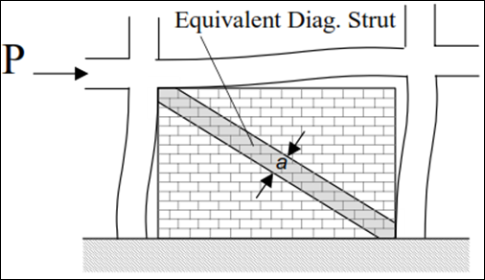
Figure 2. Equivalent strut model.
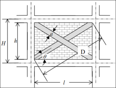
Figure 3. Strut geometry.
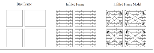
Figure 4. Structural layout of bare frame, infilled frame and infill frame model .
2.4. Mechanical Parameters of Infill Walls
2.4.1. Compressive Strength
The compressive strength fm<sub></sub> is the key parameter that primarily governs the resistance of the strut. It differs from the standard compressive strength of the masonry by considering the angle of the principal compressive stresses and the anticipated failure mode in the infill pane. Specifically, the failure theory proposed by Mann and Muller and modified by Crisafulli has been developed considering the shear and normal stresses in the bed joint Based on equilibrium conditions the following equation is obtained.
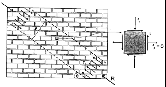
Figure 5. Representation Stress state in masonry prism .
fn=f1sin2(1)
f1sincos
f1 = fm<sub></sub> = fn/sin2 2.5MPa/sin232.8 = 8.52MPa (diagonal compressive strength of masonry panel).
2.4.2. Modulus of Elasticity
The elastic modulus Em represents the initial slope of the stress-strain curve and its values exhibits large variations. Various literatures present different approaches for computation of Em. The empirical equation proposed by Paulay and Priestley , which provide conservative value for the elastic modulus, was used in this study.
Em=750fm<sub></sub>(3)
Em=750x8.52MPa=6,390MPa
2.4.3. Vertical Separation Between Struts
Equivalent contact length (hz), introduced as percentage of the vertical height of the panel, effectively yielding the distance between the internal and dummy nodes, and used so as to take into account the contact length z between the frame and the infill panel, as defined by Stafford Smith . The vertical separation between struts leads to a reasonable results for values of 1/3 to 1/2 of the contact length. The contact length z, as defined by Stafford Smith , who introduced the dimensionless relative stiffness parameter , is given by
Z=π2λ(4)
λ=Emtwsin(2θ)4ECIChw4(5)
Where: tw, hw, and Em are the thickness, the height and the modulus of the infill respectively, ϴ is the angle between diagonal of the infill and the horizontal, Ec is the modulus of elasticity of the column, Ic is the moment of inertia of the column, is a dimensionless parameter which takes into account the effect of relative stiffness of the masonry panel to the frame.
Ec = 29,000MPa, Ic (avg.) = 2.125x109mm4, Em = 6,390MPa, tw (avg.) = 215mm, hw = 2,900mm
λ=6390*215*sin(2*32.8)4*29000*2.125*109*29004=0.001143
Z=3.142*0.001143=1,373mm
Taking the average value for hz, (1/3 to 1/2)Z, which is approximately 0.42z, the vertical separation between struts is found to be 0.42*1,373mm = 576.66mm. Since (hz) introduced as percentage of the vertical height of the panel, the value becomes 576.66/2900 = 20%. It has to be noted that the contact length is different for each side of the infill panel due to the different dimensions of the columns. In this typical model cases an average value for respective parameters is assumed as far as their variation is insignificant.
2.4.4. Area of the Strut
The area of strut Am is defined as the product of the panel thickness and the equivalent width of the strut bw, which normally varies between 10% and 40% of the diagonal of infill panel (dm) as concluded by many researchers based on experimental data and analytical results. Paulay and Priestley expression presented a conservative value for the estimation of bw.
bw=dw4(6)
Accordingly; dw (avg.) = 4.95m, and thus width and area of struts are computed as follows:
bw=4.95/4=1.24m
Amfor15x20x40cmHCB=1.24*0.19m=0.235m2
Amfor20x20x40cmHCB=1.24*0.23m=0.285m2
3. Numerical Modelling and Analysis
Pushover analyses are performed on SeismoStruct software to evaluate the lateral stiffness of the case study buildings. Five model cases were simulated for each building type (Seven-story, eleven-story and sixteen-story), consisting Bare Frame Building Model, 25% Infilled Model, 50% Infilled Model, 75% Infilled Model, and 100% Infilled Model. The software allows to numerically model all the design outputs from ETABS presented in Table 1 to Table 6. This software tool efficiently estimates deformations caused by lateral forces and is capable of accounting for both material and geometric nonlinearity. The structural response was assessed based on dominant periods, prevalent base shear, and maximum displacement at the top story.
The author of this article has previously studied the fragility analysis of HCB infilled reinforced concrete buildings and published the work on a reputable journal which can be accessed for further reference from Awayo . This study is also based on the same type of buildings to make use of actual structural design outputs for distinct performance investigation, effect of HCB on lateral stiffness of the building. Therefore, three figures below taken from SeismoStruct model are similar to the previously published work of the author.
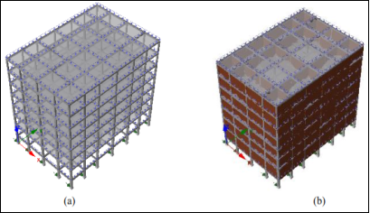
Figure 6. Numerical model of seven-story building on SeismoStruct (a) bare frame, (b) infilled frame.
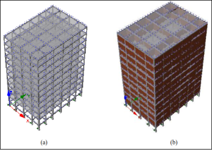
Figure 7. Numerical model of eleven-story building on SeismoStruct (a) bare frame, (b) infilled frame.
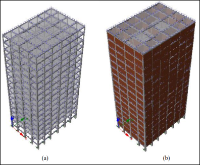
Figure 8. Numerical model of sixteen-story building on SeismoStruct (a) bare frame, (b) infilled frame.
4. Results and Discussion
4.1. Fundamental Natural Vibration Period
Determining the natural periods of a structure provides a better understanding of how it might behave under earthquake loading. These values depend entirely on the stiffness and mass of the structure. Its evaluation is an essential step in estimating the seismic response both in seismic design and assessment. The fundamental vibration period is calculated for various building model cases, and a comparative analysis is presented in the following section. Based on the monitored pushover analysis in the governing direction (+X) of the simulated three-dimensional seven-story, eleven-story and sixteen-story buildings, the following response were observed in terms of the fundamental periods.
4.1.1. Seven-story Building Model Cases
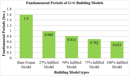
Figure 9. Fundamental periods of seven-story building models.
Bare frame building model was found to have a highest fundamental natural vibration period (i.e. 1.6 Sec.) Introducing 25% of infill panels had substantially reduced the fundamental period to 0.989 Sec (62% reduction). Similarly, introducing 50%, 75%, and 100% infills into the bare frames reduced the fundamental periods to 0.814 (97% reduction), 0.702 (128% reduction), and 0.624sec (156% reduction) respectively. It can be observed that the addition of infills to the frame reduces the fundamental periods of the structure, thereby increasing the lateral stiffness of the framing system.
4.1.2. Eleven-story Building Model Cases
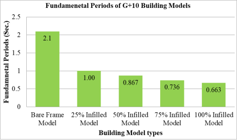
Figure 10. Fundamental periods of eleven-story building models.
Bare frame building model was found to have a highest fundamental natural vibration period (i.e. 2.1 Sec.) compared to other building model cases with varying percentages of infill panels bounded by frame elements. Introducing 25% of infill panels into the bare frame model had substantially reduced the fundamental period to 1.0 Sec (110% reduction). Increasing the percentage of infills to 50%, 75%, and 100% has reduced the fundamental periods to 0.867 (142% reduction), 0.736 (185% reduction), and 0.663 sec (217 reduction) respectively. Due to inclusion of infill walls the fundamental time period of the structures decreased in more than 110% as it was noticed in all scenarios.
4.1.3. Sixteen-story Building Model Cases
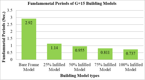
Figure 11. Fundamental periods of sixteen-story building models.
From the result, it was noted that bare frame building model was found to have a highest fundamental natural vibration period (i.e. 2.92 Sec.) compared to other building model cases with varying percentages of infill panels. A model with 25% infill had a fundamental period of 1.14 seconds, representing a 157% reduction. Adding infill percentages of 50%, 75%, and 100% to the bare frames further decreased the fundamental periods to 0.955 seconds (a 206% reduction), 0.811 seconds (a 260% reduction), and 0.737 seconds (a 296% reduction), respectively.
Generally speaking, additions of infills into the RC frame building significantly reduced the fundamental vibration period of the structure under consideration. The impact of adding infills becomes more pronounced as the number of stories increases. As observed, the percentage reductions in fundamental periods for the eleven-story building models are higher than those for the seven-story building models. Likewise, the reductions for the sixteen-story building models are greater than those for the eleven-story models. Eventually, this shows that addition of infills have more significant contributions as the story number increase there by attracting attentions in terms of stiffness and energy dissipation.
4.2. Roof Displacement and Capacity Curve
The capacity curve illustrates the relationship between the load applied to a structure and the resulting deflection as the static horizontal load is gradually increased until the structure reaches its maximum capacity. In a pushover analysis, a base shear versus roof displacement curve is generated, which helps determine the maximum base shear capacity of the structure. This curve shows how the structure responds to increasing lateral forces, with the base shear representing the total horizontal force at the base of the structure, and the roof displacement representing the lateral movement at the top. As noted, the two key parameters that contribute to generate the pushover curve are seismic base shear and roof displacement. Performing a pushover analysis on a typical structure generates a curve that shows the seismic base shear and the corresponding roof displacement at various performance levels. In this process, pushover analyses were conducted on the proposed building models, applying increasing lateral forces until the structure reached a predetermined performance level, defined by the target displacement. This helps assess the building's behavior under seismic loading and ensures it meets safety and performance requirements4.2.1. Seven-story Building Model Cases
The figure below illustrates the capacity curves generated from static pushover analysis on SeismoStruct software. The curve shows seismic base shear versus roof displacement of building model cases under varying infill percentage. It was found that seismic base shear for infilled building models are greater than bare frame building model. But the base shear of infilled models decreased abruptly to a value of about 1,000kN just after infill onset cracks where their stiffness contribution starts to degrade.
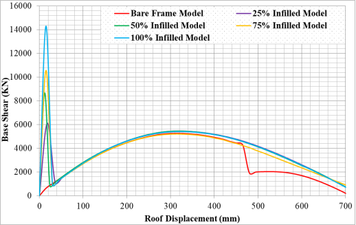
Figure 12. Capacity curves of seven-story building model cases.
Further application of static pushover load derived frame elements to their ultimate capacity and application of additional loads after this point would bring in reduction of base shear. The maximum roof displacement where the frame elements attained their ultimate strength was found to be 300mm. While infill onset-cracks was observed approximately around 17mm roof displacement and the crack propagations in infills continued along with stiffness reduction till the building roof displacement reached about 30mm.
4.2.1. Eleven-story Building Model Cases
From the analysis, it was noted that seismic base shear for infilled building models are greater than bare frame building model. But the base shear of infilled models decreased abruptly to a value of about 800kN just after infill onset cracks where their stiffness contribution starts to degrade. Also the maximum roof displacement where the frame elements attained their ultimate strength was found to be 420mm. While at approximately 20mm roof displacement infill onset-cracks was observed and the crack propagations in infills continued along with stiffness reduction till the building roof displacement reached about 30mm.
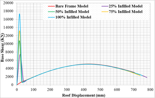
Figure 13. Capacity curves of eleven-story building model cases.
4.2.2. Sixteen-story Building Model Cases
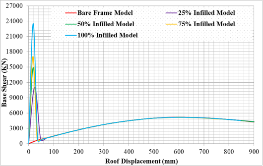
Figure 14. Capacity curves of sixteen-story building model cases.
Referring to the figures above, it was found that seismic base shear for infilled building models are greater than bare frame building model. However, the base shear of the infilled models quickly dropped to around 760kN right after the onset of infill cracking, at which point their stiffness contribution began to degrade. Also the maximum roof displacement where the frame elements attained their ultimate strength was found to be 600mm. While at approximately 24mm roof displacement infill onset-cracks was observed and the crack propagations in infills continued along with stiffness reduction till the building roof displacement reached about 50mm.
Based on the results obtained, the impact of infills added to the bare frame model has been found to be highly significant, with a substantial increase in base shear observed until the infills began to crack. A seismic base shear of 5,150kN was found at significant damage performance levels with the corresponding roof displacements of 300, 420, and 600mm for seven-story, eleven story and sixteen-story building models respectively. While their respective on set cracks of infills were observed at 17mm, 20mm and 24mm roof displacement.
5. Conclusion
In conventional design practice, the masses of infill walls are typically considered, but their lateral stiffness is often neglected. To account for the additional lateral stiffness provided by masonry infill walls, it is essential to model the infill walls together with the frame elements (such as beams and columns). The natural periods and modes of oscillation of a building are influenced by the presence of masonry infills. In this research work, static nonlinear analysis of HCB infilled RC buildings were carried out by implementing numerical models on the basis of finite element principles. Three distinct building model cases (i.e. seven-story, eleven-story and sixteen-story) each as a bare and infilled frame were studied.
Bare RC frame buildings were analyzed and designed on ETABS based on Ethiopian Buildings Code Standards (ES EN: 2015). While static pushover analysis of the designed building model cases were computed using SeismoStruct. The fundamental vibration periods and capacity curves were explicitly presented as key response parameters. Based on the building cases considered in the study, the following specific conclusions are drawn from the investigation and performance evaluation of HCB infilled RC buildings, with respect to the aforementioned performance measurement parameters in global states of response.
Results from the pushover analysis showed that additions of infills into the bounding frame significantly reduce the fundamental vibration period of the structure under consideration. Introducing 25% of infills into the frame models abruptly decreased the fundamental period with about 62% for seven-story, 110% for eleven-story and 157% for sixteen-story building models.
The addition of infills has a relatively greater impact on the fundamental period as the number of stories increases. It was observed that the percentage changes in fundamental periods for eleven-story building models are larger than those for the seven-story building models, and similarly, the changes for sixteen -story building models are greater than those for eleven-story models.
A tremendous increase in the seismic base shear was remarkable with introduction of infill panels in the building model. Since the contribution of infills is effective within their performance range (up to the onset of cracking), the seismic base shear was notably high within this range. However, a gradual decrease in base shear was observed immediately after reaching this performance point.
A seismic base shear of 5,150kN was found at significant damage performance levels with the corresponding roof displacements of 300, 420, and 600mm for seven-story, eleven-story and sixteen-story building models respectively.
Thus for relatively high rise buildings the contribution of infills in terms of stiffness and energy dissipation attracts more attentions as their contribution with respect to base shear is substantial and considerable.
6. Recommendation
Engineers are advised to find a way to account for infill walls, particularly in high-rise buildings, as the behavior of the structure differs significantly from the conventional approach.
The damping coefficient applied to concrete frames should consider the significant contribution of masonry infill walls to energy dissipation.
The stiffness of the structure can be enhanced through the proper use and arrangement of masonry infills within the bounding frames both in the plan and elevation. On the other hand, an irregular layout, such as leaving certain stories without infills, can have severe effects on the building.
Abbreviations

EN

European Norm

ES

Ethiopian Standard

ETABS

Extended Three Dimensional Analysis of Building Systems

HCB

Hollow Concrete Block

RC

Reinforced Concrete

Author Contributions
Daniel Dibaba Awayo: Conceptualization, Data curation, Formal Analysis, Methodology, Software, Writing - original draft
Yohannes Gudeta Deressa: Methodology, Supervision, Validation, Writing - review & editing
Funding
This work is not supported by any external funding.
Data Availability Statement
The data is available from the corresponding author upon reasonable request.
Conflicts of Interest
The authors declare no conflicts of interest.
References
[1] Awayo, D. D. Seismic fragility analysis of hollow concrete block infilled reinforced concrete buildings. International Research Journal of Innovations in Engineering and Technology, 2022, 06(12), 52-59.
[2] Jalaeefar, A., & Zargar, A. Effect of infill walls on behaviour of reinforced concrete special moment frames under seismic sequences. Structures, 2020, 28, 766-773.
[3] Ethiopian Standards. ES EN (1998: 2015) Ethiopian standards based on Euro norms: Design of structures for earthquake- Part 1: General rules- seismic actions and rules for buildings. Ministry of Construction.
[4] Kose, M. M. Parameters affecting the fundamental period of RC buildings with infill walls. Engineering Structures, 2009, 31(1), 93-102.
[5] Tasnimi, A. A., & Mohebkhah, A. Effect of infill vertical irregularity on seismic demands of RC buildings. In Proceedings of the 2nd International Conference on Concrete and Development, Tehran, 2005.
[6] Rajesh, C., Kumar, R., & Kandru, S. Seismic performance of RC framed buildings with and without infill walls. International Journal of Engineering Research and Technology, 2014, 3, 2278-0181.
[7] Bala Balaji, Y., Prasad, S. A. V., & Kavitha, B. Effect of infill walls on seismic performance of RC framed buildings. IOP Conference Series: Earth and Environmental Science, 2024, 1409(1), 012030.
[8] CSI. (2016). ETABS 2016 V16.2.1: Integrated building design software. Computers and Structures Inc.
[9] Ethiopian Standards. ES EN (1991: 2015) Ethiopian standards based on Euro norms: Actions on structures- Part 1-1: General actions-densities, self-weights, imposed loads for buildings. Ministry of Construction.
[10] Ethiopian Standards. ES EN (1992: 2015) Ethiopian standards based on Euro norms: Design of concrete structures - Part 1-1: General rules and rules for building. Ministry of Construction.
[11] Seismosoft. SeismoStruct v7.0 user manual, 2014, a computer program for static and dynamic nonlinear analysis of framed structures.
[12] Mann, W., & Muller, H. Failure of shear-stresses masonry - An enlarged theory, tests and application to shear walls. Proceedings of the British Ceramic Society, 1982, 30, 139-149.
[13] Crisafulli, F. J. Seismic behaviour of reinforced concrete structures with masonry infills (Doctoral dissertation, University of Canterbury, 1997).
[14] Paulay, T., & Priestley, M. J. N. Seismic design of reinforced concrete and masonry buildings. John Wiley & Sons, 1992.
[15] Stafford-Smith, B. S. (Ed.). Behaviour of square infilled frames. Journal of Structural Division, 1966, 92(381-403). ASCE.
Cite This Article
  • APA Style

    Awayo, D. D., Deressa, Y. G. (2025). Effects of Masonry Infills on the Lateral Stiffness of Reinforced Concrete Buildings. American Journal of Civil Engineering, 13(2), 68-80. https://doi.org/10.11648/j.ajce.20251302.12

    Copy | Download

    ACS Style

    Awayo, D. D.; Deressa, Y. G. Effects of Masonry Infills on the Lateral Stiffness of Reinforced Concrete Buildings. Am. J. Civ. Eng. 2025, 13(2), 68-80. doi: 10.11648/j.ajce.20251302.12

    Copy | Download

    AMA Style

    Awayo DD, Deressa YG. Effects of Masonry Infills on the Lateral Stiffness of Reinforced Concrete Buildings. Am J Civ Eng. 2025;13(2):68-80. doi: 10.11648/j.ajce.20251302.12

    Copy | Download

  • @article{10.11648/j.ajce.20251302.12,
      author = {Daniel Dibaba Awayo and Yohannes Gudeta Deressa},
      title = {Effects of Masonry Infills on the Lateral Stiffness of Reinforced Concrete Buildings
    },
      journal = {American Journal of Civil Engineering},
      volume = {13},
      number = {2},
      pages = {68-80},
      doi = {10.11648/j.ajce.20251302.12},
      url = {https://doi.org/10.11648/j.ajce.20251302.12},
      eprint = {https://article.sciencepublishinggroup.com/pdf/10.11648.j.ajce.20251302.12},
      abstract = {Block infills are usually regarded as non-loadbearing components in buildings, and are frequently neglected in the analysis and design of building structures. The main objective of this study is to perform static nonlinear analysis of hollow concrete block (HCB) infilled reinforced concrete buildings (RC) subjected to a seismic excitation. For this study, three different buildings were selected as case studies: a seven-story, an eleven-story, and a sixteen-story building, each with a standard floor plan. Bare RC frame buildings were analyzed and designed on ETABS based on Ethiopian Buildings Code Standards (ES EN: 2015). While numerical modeling and static pushover analysis of the designed building model cases were computed using SeismoStruct. The masonry panel model was employed to reproduce the behaviour of the full-scale infilled frame model using diagonal compression struts. The results from the pushover analysis were used to determine the fundamental vibration period and generate the capacity curves. It was observed that the presence of infills had a highly significant impact, causing a considerable increase in base shear until the infills began to crack. Additionally, the infills played a major role in reducing the fundamental vibration period of the structures. A seismic base shear of 5,150kN was found at significant damage performance levels with the corresponding roof displacements of 300, 420, and 600mm for seven-story, eleven-story and sixteen-story building models respectively. While their respective on set cracks of infills were observed at 17mm, 20mm and 24mm roof displacement. Therefore, for relatively high-rise buildings, the contribution of infills in terms of stiffness and energy dissipation becomes more important, as their impact on base shear and fundamental period is both substantial and significant.
    },
     year = {2025}
    }
    

    Copy | Download

  • TY  - JOUR
    T1  - Effects of Masonry Infills on the Lateral Stiffness of Reinforced Concrete Buildings
    
    AU  - Daniel Dibaba Awayo
    AU  - Yohannes Gudeta Deressa
    Y1  - 2025/03/31
    PY  - 2025
    N1  - https://doi.org/10.11648/j.ajce.20251302.12
    DO  - 10.11648/j.ajce.20251302.12
    T2  - American Journal of Civil Engineering
    JF  - American Journal of Civil Engineering
    JO  - American Journal of Civil Engineering
    SP  - 68
    EP  - 80
    PB  - Science Publishing Group
    SN  - 2330-8737
    UR  - https://doi.org/10.11648/j.ajce.20251302.12
    AB  - Block infills are usually regarded as non-loadbearing components in buildings, and are frequently neglected in the analysis and design of building structures. The main objective of this study is to perform static nonlinear analysis of hollow concrete block (HCB) infilled reinforced concrete buildings (RC) subjected to a seismic excitation. For this study, three different buildings were selected as case studies: a seven-story, an eleven-story, and a sixteen-story building, each with a standard floor plan. Bare RC frame buildings were analyzed and designed on ETABS based on Ethiopian Buildings Code Standards (ES EN: 2015). While numerical modeling and static pushover analysis of the designed building model cases were computed using SeismoStruct. The masonry panel model was employed to reproduce the behaviour of the full-scale infilled frame model using diagonal compression struts. The results from the pushover analysis were used to determine the fundamental vibration period and generate the capacity curves. It was observed that the presence of infills had a highly significant impact, causing a considerable increase in base shear until the infills began to crack. Additionally, the infills played a major role in reducing the fundamental vibration period of the structures. A seismic base shear of 5,150kN was found at significant damage performance levels with the corresponding roof displacements of 300, 420, and 600mm for seven-story, eleven-story and sixteen-story building models respectively. While their respective on set cracks of infills were observed at 17mm, 20mm and 24mm roof displacement. Therefore, for relatively high-rise buildings, the contribution of infills in terms of stiffness and energy dissipation becomes more important, as their impact on base shear and fundamental period is both substantial and significant.
    
    VL  - 13
    IS  - 2
    ER  - 

    Copy | Download

Author Information