Research Article | | Peer-Reviewed

A Comparative Study on Seismic Strengthening of Reinforced Concrete Beam–Structural Wall Joints Using External Stiffeners Plate, Basaltic Fiber and CFRP

Received: 5 January 2026     Accepted: 26 January 2026     Published: 10 April 2026
Views:       Downloads:
Abstract

The existing structure might not have enough seismic resistance capacities due to construction errors, design by old building design codes (EBCS 1995), deterioration, and building function changes. To increase the seismic resistance capacity of Reinforced Concrete (RC) structures, many studies recommend different strengthening methods. Those strengthening methods have different costs, strengthening capacities, and availabilities. To identify the best, strengthening methods it needs further investigations. Most previous studies were conducted on the detailed application of individual strengthening applications. There are no previous studies that have done a comparative study on the seismic strengthening of reinforced concrete beam–structural wall joints using external stiffener plates, Basaltic Fiber Reinforced Polymer (BFRP), and Carbon Fiber Reinforced Polymer (CFRP). The main aim of this study is a comparative study on the seismic strengthening of reinforced concrete beam–structural wall joints using an external stiffener plate, BFRP and CFRP. The experimental work presented in the literature was used for validation of finite element analysis to ensure the accuracy of developed finite element models and further investigations. The numerical investigation of a comparative study on the seismic strengthening of reinforced concrete beam–structural wall joints using external stiffener plates, basaltic fiber, and CFRP has been done with the comparison of load resistance capacities. The numerical study will be done using ANSYS 22R1 mechanical APDL nonlinear software program. The finite element analysis result shows that, for both CFRP and BFRP from 0°, 45° & 90° layer orientations of CFRP strengthening methods, 90° CFRP layer orientation shows better improvement of ultimate load resistance capacity. The 90° layer orientation strengthening layout increased the load-carrying capacity of the beam-shear wall connection by 30% and 26.4% for CFRP and BFRP respectively. For both CFRP and BFRP strengthening mechanisms with 90° orientation, three number of layers and 90°, 90°& 90° configuration best fiber lay out for strengthening of beam – shear wall joint. From the three beam -shear wall strengthening mechanisms of stiffener plate, CFRP and BFRP, the stiffener plate shows better performance. The stiffener plate increases the lateral load resistance capacity of the existing beam- shear wall joint by 37% - 66%.

Published in American Journal of Mechanical and Materials Engineering (Volume 10, Issue 2)
DOI 10.11648/j.ajmme.20261002.11
Page(s) 34-47
Creative Commons

This is an Open Access article, distributed under the terms of the Creative Commons Attribution 4.0 International License (http://creativecommons.org/licenses/by/4.0/), which permits unrestricted use, distribution and reproduction in any medium or format, provided the original work is properly cited.

Copyright

Copyright © The Author(s), 2026. Published by Science Publishing Group

Keywords

ANSYS, Beam–Wall Joint, External Strengthening Steel Plate, BFRP, CFRP

1. Introduction
The reinforced concrete beam–structural wall joints are critical components influencing the seismic performance of RC buildings. Due to deficiencies in design and construction practices, many existing structures lack sufficient lateral load resistance. This paper evaluates and compares the seismic performance improvement offered by three external strengthening methods: stiffener steel plates, carbon fiber-reinforced polymer (CFRP), and basalt fiber-reinforced polymer (BFRP).
The beam – wall joint regions were highly affected by the applied seismic load effect compared to other structural parts of the frame elements. Seismic retrofitting is the modification of structures to make them more resistant to seismic activity . Many previous studies were available in the literature that study the strengthening mechanisms of reinforced concrete connections. Fiber-reinforced polymers (FRP) have been used extensively for the repair and retrofit of pre-1970 RC moment resisting frames in the aftermath of the 2009 L’Aquila and 2011Christ church earthquake and often proved more cost-efficient than alternative retrofits . Basalt fiber reinforced polymer (BFRP) is a relatively new trend in the use of environmentally benign, natural fibers as reinforcement in the manufacturing of lightweight, low-cost polymer composites around the world. Although, the interest such material is currently being widely used basalt fiber, which is cost-effective offers exceptional behavior over glass fiber, and is less expensive than carbon fiber . The CFRP has a high strength-to-weight ratio and corrosion resistance making FRPs particularly attractive as retrofit materials . Study , analyzed the flexural strengthening of the RC beam column joints using an innovative anchorage system.
The researchers conducted an experimental work to review the retrofitting of reinforced concrete elements using FRP. The study presented an experimental study used to assess the behavior of beams wrapped with GFRP, CFRP, and BFRP bidirectional mats. Research , investigated experimental studies on the seismic behavior of reinforced concrete beam-column joints strengthened with basalt fiber-reinforced polymer sheets.
Research [8] studied an experimental and numerical study for the cyclic structural performance of RC exterior beam-column joints strengthened using CFRP sheets. Study investigated the effectiveness of composite fiber-reinforced polymer (CFRP) layers for exterior beam-column connections and were studied through a finite element model (FEM).
The research studied the Seismic retrofit of deficient exterior RC beam-column joints using steel plates and angles. Six half-scale exterior RC beam-column joints were tested under quasistatic cyclic loading with a constant axial load on the column. , studied the strengthening of the precast beam-column joint using steel encasement.
2. Materials and Methods
The finite element method (FEM) was adopted using ANSYS 22R1 to model the beam–wall joints. Validation was done against the experimental data of . Three strengthening schemes—external steel plates, CFRP sheets, and BFRP composites—were modeled with varying layer orientations, thicknesses, and material grades. Material properties followed .
3. Results and Discussion
3.1. Verification of Finite Element Analysis Results
The validation of FEA has been done by comparing the previous experimental works' test results. The verification of non-linear finite element analysis has been done with the same physical characteristics such as material properties, loading conditions, geometry, and all other model parameters. The comparison of experimental work and FEA results was expressed in terms of force-displacement responses and failure modes.
3.1.1. Load–Displacement Response
The force-displacement plot of the FEA and the experimental results of , shows good agreement with the 20mm mesh size. The analysis result of the finite element method is greater than the experimental method at ultimate load resist capacity. The experimental analysis results also show that the maximum value at first ultimate capacity decreases gradually. The ultimate load-resistant capacity of both results shows good agreement with the percentage differences of 1.4%. In addition, the ductility and stiffness of both results also show similar values (Figure 1).
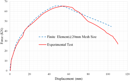
Figure 1. Experimental and finite element load-displacement responses.
3.1.2. Failure Modes
As shown in Figure 2 the concrete damage occurred at the shear wall joint. As testing continued, damage extended toward the middle of the beam section and penetrated the concrete core. The formation of hairline diagonal cracks in the joint region has occurred (Figure 2a & 2b). As the applied load increases the spalling and crushing of the concrete cover are displayed. The yield of longitudinal reinforcement was observed in at shear wall joint of the specimens as shown in Figure 2c. The experimental result shows that crack widths at the joint interface were 0.125in. (3.2mm), and the first sign of joint interface deterioration was perceived. This deterioration increased in the second cycle. At a drift ratio of 3.125%, signs of punching of one side of the beam through the wall web were observed with a 50% increase in average crack width at the joint interface. The average crack width was 0.125in. (3.18mm) in the wall web around the joint. In the subsequent cycle of the same drift ratio, substantial strength and stiffness degradation were observed due to considerable punching deterioration. Some concrete in the joint interface crumbled, whereas the boundary elements stayed intact. Similarly, the FEA model created with the ANSYS 22R1 package was able to capture those failures and damages in a similar location of the beam-shear wall joint with a maximum equivalent plastic strain of 0.86mm. The maximum plastic strain values of concrete and reinforcements are greater than zero this indicates that the beam-wall joint has failed in the same location of experimental damage results (Figure 2).
Therefore, this validation study shows good agreement between finite element analysis and experimental test results. In this section, the accuracy of the finite element analysis is calibrated and can be posed for further numerical investigation.
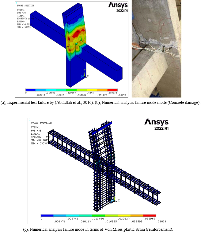
Figure 2. (a), (b) & (C); Experimental and numerical study failure modes.
3.2. Effect of Stiffener Steel Plate Material Grade and Thickness on Load Resistances Reinforced Concrete Beam-Shear Wall Joints
3.2.1. Effect of External Strengthening Stiffener Steel Plate Material Grade on Load Resistances Reinforced Concrete Beam–Shear Wall Joints
The effect of stiffener steel plate material grade has been investigated using a constant, 30mm displacement control load at the top of the wall. The thickness of the plate has been taken as 3mm and the material grade varied as S- 235 MPa, S- 275 MPa, S- 355 MPa, and S- 450 MPa. The finite element analysis result was discussed in terms of force-displacement responses as presented in Figure 3.
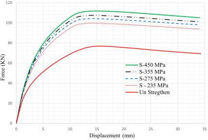
Figure 3. Force–displacement responses of bream–shear wall joint strengthened with the variation of stiffener steel plate material grade.
Forces – Displacement Response
The load resistance of reinforced concrete beam-shear wall joints strengthened by external stiffener steel plates using different material grades was discussed in Figure 3. The finite element analysis result shows that for stiffener plate material grade varies as S- 235 MPa, S- 275 MPa, S- 355 MPa and S- 450 MPa, the lateral load resistance capacity of existing beam- shear wall joint is increased by 29.8%, 35.7%, 39.9%, and 45.3% respectively from strengthen capacity of beam-shear wall joints of 76.73 KN at the 3mm thickness stiffener plate. This indicates that the stiffener plate material grade variation has considerable effects on the lateral load resistance capacity of strengthening beam-shear wall joints. In general, based on this finite element analysis result increasing stiffener steel plate material grade varies from S- 235 MPa to S- 450 MPa, and the load resistance capacity of beam-shear wall joint increased by 16%. Therefore, to get a higher resistance capacity, strengthening by S- 450 MPa plate material strength is better than the other material strengths.
3.2.2. Effect of External Strengthening Stiffener Steel Plate Thickness on Load Resistances Reinforced Concrete Beam–Shear Wall Joints
To conduct the effect of stiffener steel plate thickness, a constant, 30mm displacement control load was at the top of the wall, The material grade of the plate has been taken as S- 450 MPa and the plate thickness varied as 1mm, 2mm, 3mm, 5mm, and 10mm. The finite element analysis result was discussed in terms of force-displacement responses as presented in Figure 4.
Forces – Displacement Response
In this section, the effects of external strengthening stiffener steel plate thickness on load resistance reinforced concrete beam-shear wall joints are illustrated in Figure 4. The finite element analysis result shows that for stiffener plate thickness varies as 1mm, 2mm, 3mm, 5mm, and 10mm, the lateral load resistance capacity of existing beam-shear wall joint is increased by 37%, 42.6%, 45.5%, 50.44%, and 66% respectively from the unstrengthened capacity of beam-shear wall joints at S-450 MPa material grade. This indicates that the stiffener plate thickness variation has significant effects on the lateral load resistance capacity of strengthing beam-shear wall joints. In general, based on this analysis results, increasing stiffener steel plate thickness from 1mm to 10mm, the load resistance capacity of the beam-shear wall joint increased by 29%. Therefore, to increase the load resistance capacity of beam-shear wall joint by more than 50%, the stiffener plate thickness must be more than 5mm.
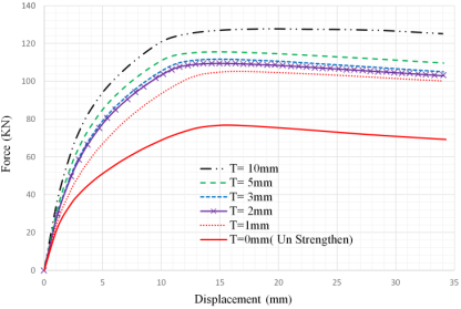
Figure 4. Force–displacement responses of bream–shear wall joint strengthened with variation stiffener steel plate thickness.
3.3. Investigation of CFRP Strengthening Mechanisms
3.3.1. CFRP Sheet Orientation
To identify the best orientation of CFRP strengthening methods that increase more amount of load resistance capacity, the CFRP with 0, 45, and 90 orientations in one layer have been investigated. The CFRP sheet is attached to in same location of plate strengthen. The effect of CFRP orientations on load-displacement responses of beam–shear wall joints has been presented in Figure 5. The load-carrying capacity of beam-shear wall connection is increased by 15.2%, 20.6%, and 30% for CFRP strengthen with 0, 45 and 90 orientations respectively. This investigation result shows that the 90 fiber orientation has a higher load resistance capacity than the other two orientations. The CFRP with 0 fiber orientation gives a low load resistance capacity compared to 45 and 90 fiber orientation. Based on this investigation, from different types of orientations of CFRP strengthening method, 90orientation is proposed.
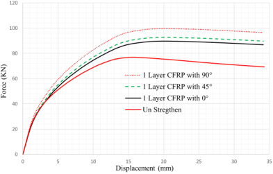
Figure 5. Beam-shear wall connection strengthened with different orientations of CFRP.
3.3.2. CFRP Number of Layers
To select a suitable number of CFRP layers for strengthening methods that increase more amount of load resistance capacity, CFRP with one-layer, two-layer, and three layers at 90-degree fiber orientation has been investigated. The effect of CFRP number of layers in load-displacement response graphs are presented in Figure 6. The load-carrying capacity of one, two, and three layers are recorded as 98.9KN, 103.3KN, and 105.3KN respectively. With the use of one, two, and three layers of the CFRP sheet, the load resistance capacity is increased by 30%, 34.63%, and 37.23% respectively. This shows that the beam -shear wall joint load resistance capacity increases as the number of CFRP layers increases.
In this study, three-layer (3) CFRP strengthening is proposed based on load resistance capacity.
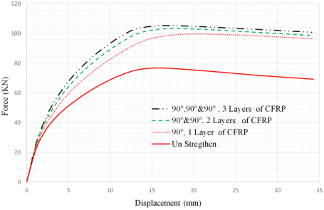
Figure 6. Beam-shear wall connection strengthened with different number of layers of CFRP.
3.3.3. CFRP Sheet Configuration
In addition to the effect of number of layers and orientation, the effect of CFRP configuration has been investigated. This investigation is conducted with seven (7) models of beam- shear wall joints. Different combination of orientation (configuration) has different load resistance capacities when more than one CFRP layer is used. The effect of different configurations of CFRP at three CFRP layers of 0, 45, and 90 orientation is shown in Figure 7.
Among different configurations of the CFRP strengthening method, the beam-shear wall joint strengthened with CFRP by a configuration of “90, 90, and 90” layout, shows better improvement in load resistance capacity. This configuration increases the load resistance capacity by 37.23% from the unstrengthen load resistance capacity of 76.73KN. The minimum result is obtained at CFRP strengthened by the configuration of “0, 0, 0”. CFRP strengthened using this configuration, the load resistance capacity increased by 23.4% of the reduced lateral load resistance capacity. Therefore, to strengthen beam–shear wall joint with CFRP, “90, 90, and 90” configurations are proposed because of the highest load resistance capacity and batter stiffness compared to the other three-layer configurations.
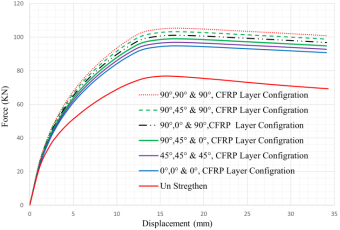
Figure 7. Beam-shear wall connection strengthened with different configurations of CFRP.
3.4. Investigation of BFRP Strengthening Mechanisms
3.4.1. BFRP Sheet Orientation
To select the best orientation of BFRP strengthening methods that increases more amount of load resistance capacity, the BFRP with 0, 45, and 90 orientations in one layer have been conducted. The BFRP sheet is attached to in same location of plate strengthen. The effect of BFRP orientations on load-displacement responses of beam–shear wall joints has been presented in Figure 8. The load-carrying capacity of beam-shear wall connection increased by 14.1%, 18.5, and 26.4% for BFRP strengthen with 0, 45 and 90 orientations respectively. This study result shows that the 90 fiber orientation has a higher load resistance capacity than the other two orientations. The BFRP with 0 fiber orientation gives a low load resistance capacity compared to 45 and 90 fiber orientation. Based on this investigation, from three types of orientations of the BFRP strengthening method, 90 orientation is proposed.
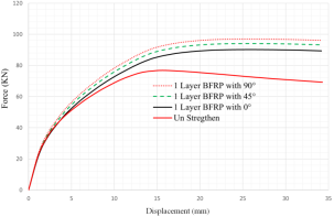
Figure 8. Beam-shear wall connection strengthened with different orientations of BFRP.
3.4.2. BFRP Number of Layers
To identify the suitable number of BFRP layers for strengthening methods that increase more amount of load resistance capacity, BFRP with one-layer, two-layer, and three layers at 90-degree fiber orientation has been studied. The effect of BFRP number of layers in load-displacement response graphs are discussed in Figure 9. With the application of one, two, and three layers of the BFRP sheet, the load resistance capacity is increased by 14.1%, 32.32%, and 35.23% respectively. This shows that the beam-shear wall joint load resistance capacity increases as the number of BFRP layers is increases. In this study also, three-layer (3) BFRP strengthening is proposed based on load resistance capacity.
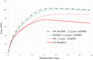
Figure 9. Beam-shear wall connection strengthened with different number of layers of BFRP.
3.4.3. BFRP Sheet Configuration
In this section, the effect of BFRP configuration has been investigated in Figure 10. This investigation is conducted on seven (7) models of beam-shear wall joints strengthened with a different configuration of BFRP. Different combination of orientation (configuration) has different load resistance capacities when more than one number of BFRP layers is used. The effect of different configurations of BFRP at three BFRP layers of 0, 45, and 90 orientation is shown in Figure 10.
Among different configurations of the BFRP strengthening method, the beam-shear wall joint strengthened with BFRP by a configuration of “90, 90, and 90” layout, shows better improvement in load resistance capacity. This configuration increases the load resistance capacity by 35.23% from the unstrengthen load resistance capacity of 76.73KN. The minimum result is obtained at BFRP strengthened by the configuration of “0, 0, 0”. BFRP strengthened using this configuration, the load resistance capacity increased by 21.5% of the reduced lateral load resistance capacity. Therefore, to strengthen beam–shear wall joint with BFRP, “90, 90, and 90” configurations are proposed because of the highest load resistance capacity and batter stiffness compared to the other three-layer configurations.
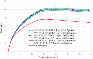
Figure 10. Beam-shear wall connection strengthened with different configurations of BFRP.
3.5. Comparison of Strengthening Mechanisms
In this section, to select the best strengthening mechanisms, the comparison studies were conducted on stiffener steel plate, CFRP, and BFRP as illustrated in sections 4.5.1, 4.5.2, and 4.5.3. in terms of load-displacement response, concrete damage, and plastic strain respectively. The comparison studies were conducted by selecting the proposed strengthening methods from individual studies.
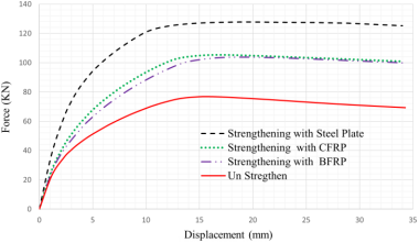
Figure 11. Comparison of beam–shear wall joint strengthen mechanisms.
3.5.1. Load–Displacement Response
The load-displacement responses of the stiffener plate, CFRP, and BFRP strengthened beam–shear wall have been discussed in Figure 11. The finite element analysis result shows that beam–shear wall joint strengthened with a stiffener plate, CFRP and BFRP increases the lateral load resistance capacity of 76.73 KN by 66%, 37.3%, and 35.23% respectively. Based on this investigation result, the strengthening of beam–shear wall joint using a stiffener plate is better than CFRP and BFRP strengthening methods. The small values of load-resistance capacity recorded beam–shear wall joint strengthened by BFRP strengthen methods. This study recommended the Stiffener plate strengthen methods because of the strengthened capacity and availability.
3.5.2. Concrete Damage Failure Modes
The failure mode of the concrete element was expressed in terms of maximum tensile and compressive damage plasticity stress result. The maximum tensile damage plasticity stress has occurred at the wall joint as illustrated in Figure 12. and it expands towards the beam joint. The maximum tensile damage resistance capacity of externally strengthened beam-shear wall joints was increased by 2.7%, 2.48%, and 2.23% for beam-shear wall joints strengthened by stiffener plate, CFRP, and BFRP respectively. Figure 12, shows the application strengthens mechanisms changes the critical failure locations, and redistributes it to the other parts. Even though the tensile load resistance capacities of the three strengthen mechanisms have no significant difference, the stiffener plate resistance capacities are 0.22% and 0.47% better than the CFRP and BFRP respectively.
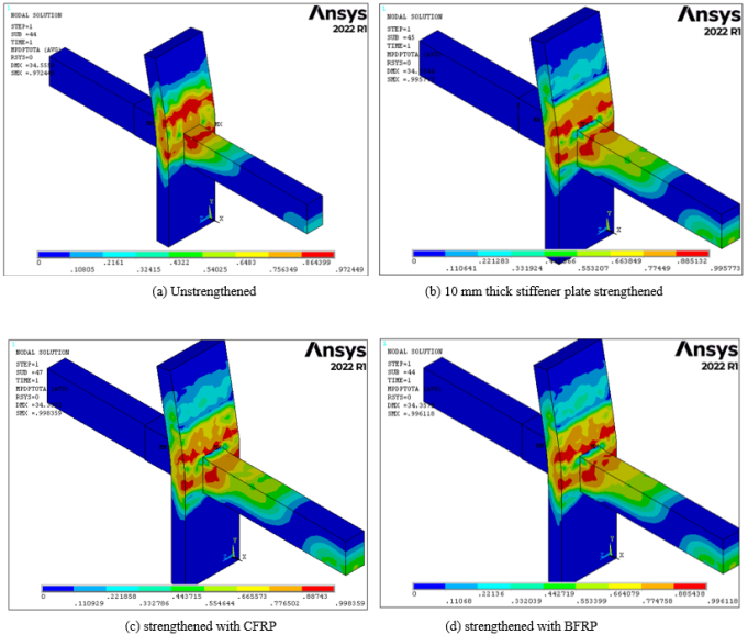
Figure 12. (a), (b), (c) & (d); Tensile and compressive concrete damage frailer mode of beam-shear wall joint strengthening mechanisms.
3.5.3. Concrete Failure Modes in Terms of First Principal Plastic Strain
The maximum first principal plastic strain has occurred at the shear wall joint above the beam before strengthening. After strengthening the maximum first principal plastic strain location changed into beam–shear wall joint on the side of beam as presented in Figure 13. The maximum first principal plastic strain values of externally strengthened beam-shear wall joints were decreased by 5.32%, 7.34%, and 9.22% for beam-shear wall joints strengthened by stiffener plate, CFRP, and BFRP respectively. The values of the first principal plastic strain values are greater than zero. This indicates the formation of cracks in all analyzed models is at beam-shear wall joints. However, the principal plastic strain has occurred in the stiffener plate at beam-shear wall joint, the principal plastic strain resistance capacity of stiffener plate is greater than both CFRP and BFRP strengthening mechanisms. If the availability of CFRP and BFRP strengthening mechanisms are good, they can be an alternative strengthen mechanisms next to the stiffener plate.
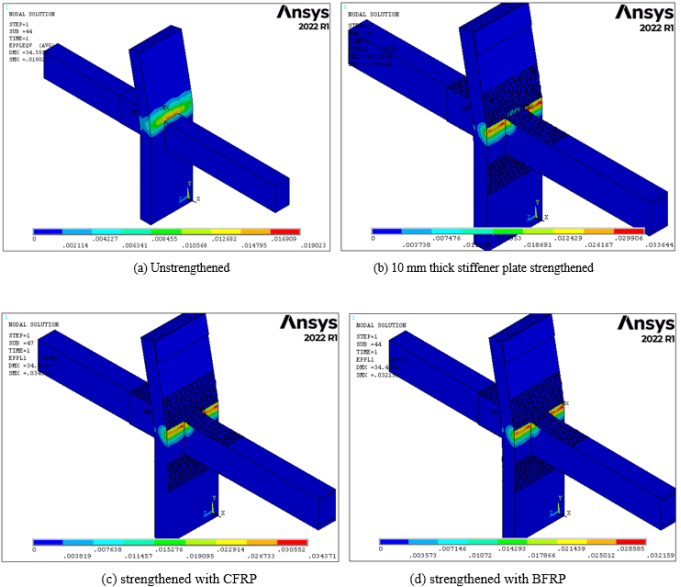
Figure 13. (a), (b), (c) & (d); First principal plastic strain concrete damage failer mode of beam-shear wall joint strengthen mechanisms.
3.5.4. Reinforcement Failure Modes in Terms of Vonmises Plastic Strain
The Von Mises plastic strain intensity is maximum at the shear wall joint in Figure 14. The maximum plastic strain of the unstrengthened beam-shear wall joint was decreased by 10%, 9.3%, and 9.18% for beam-shear wall joint strengthened by stiffener plate, CFRP, and BFRP respectively. The maximum plastic strain intensity value of all failure models was greater than zero, this indicates that in all models the yielding of reinforcement has occurred perpendicular to the maximum plastic strain of the shear wall joint. This investigation recommends that the stiffener plate strengthening mechanism increase the strain resistance capacities.
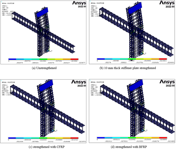
Figure 14. (a), (b), (c) & (d); Concrete damage failer mode of beam-shear wall joint strengthen mechanisms.
3.5.5. Bending Stress Response
In this specific section, the bending stress responses of beam–shear wall joints are presented in Figure 15. The bending stress effect of beam-shear wall joint is displayed at the shear wall joint. The maximum bending stress resistance capacity of externally strengthened beam-shear wall joints was increased by 28.2%, 42.4%, and 32.66% for beam-shear wall joints strengthened by stiffener plate, CFRP, and BFRP respectively. The CFRP strengthening mechanism shows better bending stress resistance capacities compared to BRFP and stiffener plate strengthening mechanisms. Whereas strengthening with an external stiffener plate has low bending resistance capacities. Therefore to resist bending stress failure the CFRP strengthening mechanism is recommended.
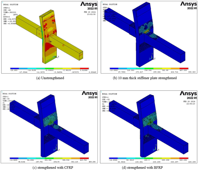
Figure 15. (a), (b), (c) & (d); Bending stress response of beam-shear wall joint strengthening mechanisms.
3.5.6. Shear Stress Response
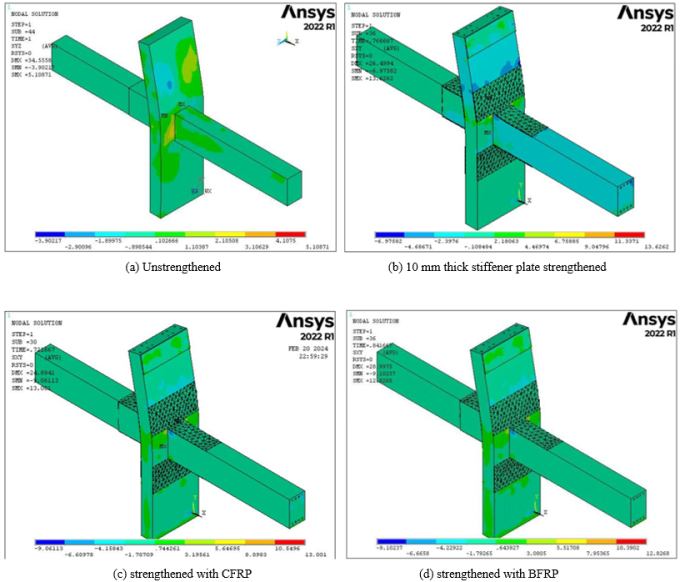
Figure 16. (a), (b), (c) & (d); Shear stress responses of beam-shear wall joint strengthening mechanisms.
In Figure 16, the shear stress responses of beam–shear wall joints are presented. The shear stress effect of beam-shear wall joints is not significant compared to other modes of failure. The maximum shear stress resistance capacity of externally strengthened beam-shear wall joints was increased by 66.17%, 59.3%, and 46.7% for beam-shear wall joints strengthened by stiffener plate, CFRP, and BFRP respectively. The external stiffener plate strengthening mechanism shows good shear stress resistance capacities compared to CFRP and BRFP strengthening mechanisms. Whereas strengthening with CFRP and BFRP has low shear resistance capacities. Therefore to resist shear stress failure the external stiffener plate strengthening mechanism is recommended.
4. Conclusion
In this thesis, the structural performance of RC frame beam-shear wall joints strengthened by an external stiffener plate, CFRP, and BFRP has been investigated. The investigation results were summarized as follows:
The load resistance capacity of beam-shear wall joints increased by 16% when stiffener steel plate material grade varies from S - 235 MPa to S - 450 MPa.
The stiffener plate increases the lateral load resistance capacity of the existing beam-shear wall joint by 37%, 42.6%, 45.5%, 50.44%, and 66%, when the plate thickness varies as: 1mm, 2mm, 3mm, 5mm, and 10mm, respectively at S-450 MPa material grade.
For Both CFRP and BFRP, from 0, 45 & 90 layer orientations of CFRP strengthening methods, 90 CFRP layer orientation shows better improvement of ultimate load resistance capacity.
For CFRP strengthen with 0, 45 and 90 orientations, the load-carrying capacity of beam-shear wall connection increased by 15.2%, 20.6%, and 30% respectively.
The load-carrying capacity of beam-shear wall connection increased by 14.1%, 18.5, and 26.4% for BFRP strengthen with 0, 45 and 90 orientations respectively.
As the strengthening number of fiber increases, the load resistance capacities increase by 30%, 34.63%, & 37.23%, and 14.1%, 32.32%, & 35.23% for 1, 2, and 3 layers of CFRP and BFRP respectively.
For strengthening of beam-shear wall joint with CFRP and BFRP, 90 fiber orientation, three number of layers, and 90°, 90°& 90° configuration is proposed.
Among beam-shear wall joint strengthening mechanisms of stiffener plate, CFRP, and BFRP, the stiffener plate shows best performance.
The BFRP strengthen mechanism has lower resistance capacities than CFRP and stiffener plates for strengthening of beam-shear wall joint.
Abbreviations

APDL

Analysis Parametric Design Language

FEM

Finite Element Method

E

Modulus of Elasticity

BFRP

Basaltic Fiber Reinforced Polymer

CFRP

Carbon Fiber Reinforced Polymer

GFRP

Glass Fiber Reinforced Polymer

Ey

Modulus of Elasticity in y-direction

Ez

Modulus of Elasticity in z-direction

PRxy

Poison’s Ratio in xy Direction

PRxz

Poison’s Ratio in xz Direction

PRyz

Poison’s Ratio in yz Direction

Gx

Shear Modulus in x- direction

Gy

Shear Modulus in y- direction

Gz

Shear Modulus in z- direction

Acknowledgments
The author expresses gratitude to Dr. Utino Worabo and Mr. Wassihun. for their guidance and technical support. Special thanks are also due to Bahir Dar Institute of Technology for providing resources and facilities.
Data Availability Statement
All data generated or analyzed during this study are included in this published article.
Conflicts of Interest
The authors declare no conflicts of interest.
References
[1] C. S. &. S. M. M. Sumaya, STRENGTHENING OF PRECAST BEAM-COLUMN JOINT USING STEEL ENCASEMENT., 2022.
[2] M. D. V. C. D. L. M. D. P. A. &. M. G. (. D. V. e. a. .. Ludovico, Analytical model and design approach for FRP strengthening of non-conforming RC corner beam-column joints Analytical model and design approach or FRP strengthening of non-conforming RC corner beam - column joints., 2016.
[3] Q. &. Z. Y. Ma, Experimental research on the microstructure and compressive and tensile properties of nano-SiO2 concrete containing basalt fibers. Underground Space (China), 2(3), 175-181., 2017.
[4] K. K. &. S. S. A. Ghosh, Seismic upgrade with carbon fiber-reinforced polymer of columns containing lap-spliced reinforcing bars. ACI Structural Journal, 104(2), 227-236., 2007.
[5] D. A. A. &. E. A. Mostofinejad, Estimating the Seismic Performance of CFRP-Retrofitted RC Beam-Column Connections Using Fiber-Section Analysis. Journal of Earthquake Engineering, 22(6), 1092-1110., 2018.
[6] S. K. S. L. N. &. K. C. Durgadevi, A review on retrofitting of reinforced concrete elements using FRP. Materials Today: Proceedings, 45(xxxx), 1050-1054., 2021.
[7] D. L. M. K. J. L. C. &. L. C. Shen, Experimental studies on the seismic behavior of reinforced concrete beam-column joints strengthened with basalt fiber-reinforced polymer sheets. Construction and Building Materials, 287, 122901., 2021.
[8] M. A. S. A. A. K. T. M. E.-s. G. &. S. M. A. Sakr, Studying Behavior of Exterior RC Beam - Column Joints Strengthened Using CFRP for Achieving “ Strong Column - Weak Beam ” In RC Frames. 4480(2), 53-68., 2019.
[9] H. Sinaei., Numerical investigation on exterior reinforced concrete Beam-Column joint strengthened by composite fiber reinforced polymer (CFRP). International Journal of the Physical Sciences, 6(28), 6572-6579., 2011.
[10] M. E. T. A. M. &. A. M. Z. Shoukry, Seismic retrofit of deficient exterior RC beam-column joints using steel plates and angles. Alexandria Engineering Journal, 61(4), 3147-3164., 2022.
[11] S. A.-S. N. &. N. D. Abdullah, Experimental study of nonplanar wall-to-beam connections under cyclic loading. ACI Structural Journal, 113(4), 655-664.
[12] Ethiopian building code of standared based on Europian norm three, (n.d.). Ethiopian building code of standared based on Europian norm three for steel structure design, ESEN 1993/2015., 1993/2015.
Cite This Article
  • APA Style

    Mulugeta, Y., Worabo, U. (2026). A Comparative Study on Seismic Strengthening of Reinforced Concrete Beam–Structural Wall Joints Using External Stiffeners Plate, Basaltic Fiber and CFRP. American Journal of Mechanical and Materials Engineering, 10(2), 34-47. https://doi.org/10.11648/j.ajmme.20261002.11

    Copy | Download

    ACS Style

    Mulugeta, Y.; Worabo, U. A Comparative Study on Seismic Strengthening of Reinforced Concrete Beam–Structural Wall Joints Using External Stiffeners Plate, Basaltic Fiber and CFRP. Am. J. Mech. Mater. Eng. 2026, 10(2), 34-47. doi: 10.11648/j.ajmme.20261002.11

    Copy | Download

    AMA Style

    Mulugeta Y, Worabo U. A Comparative Study on Seismic Strengthening of Reinforced Concrete Beam–Structural Wall Joints Using External Stiffeners Plate, Basaltic Fiber and CFRP. Am J Mech Mater Eng. 2026;10(2):34-47. doi: 10.11648/j.ajmme.20261002.11

    Copy | Download

  • @article{10.11648/j.ajmme.20261002.11,
      author = {Yosef Mulugeta and Utino Worabo},
      title = {A Comparative Study on Seismic Strengthening of Reinforced Concrete Beam–Structural Wall Joints Using External Stiffeners Plate, Basaltic Fiber and CFRP},
      journal = {American Journal of Mechanical and Materials Engineering},
      volume = {10},
      number = {2},
      pages = {34-47},
      doi = {10.11648/j.ajmme.20261002.11},
      url = {https://doi.org/10.11648/j.ajmme.20261002.11},
      eprint = {https://article.sciencepublishinggroup.com/pdf/10.11648.j.ajmme.20261002.11},
      abstract = {The existing structure might not have enough seismic resistance capacities due to construction errors, design by old building design codes (EBCS 1995), deterioration, and building function changes. To increase the seismic resistance capacity of Reinforced Concrete (RC) structures, many studies recommend different strengthening methods. Those strengthening methods have different costs, strengthening capacities, and availabilities. To identify the best, strengthening methods it needs further investigations. Most previous studies were conducted on the detailed application of individual strengthening applications. There are no previous studies that have done a comparative study on the seismic strengthening of reinforced concrete beam–structural wall joints using external stiffener plates, Basaltic Fiber Reinforced Polymer (BFRP), and Carbon Fiber Reinforced Polymer (CFRP). The main aim of this study is a comparative study on the seismic strengthening of reinforced concrete beam–structural wall joints using an external stiffener plate, BFRP and CFRP. The experimental work presented in the literature was used for validation of finite element analysis to ensure the accuracy of developed finite element models and further investigations. The numerical investigation of a comparative study on the seismic strengthening of reinforced concrete beam–structural wall joints using external stiffener plates, basaltic fiber, and CFRP has been done with the comparison of load resistance capacities. The numerical study will be done using ANSYS 22R1 mechanical APDL nonlinear software program. The finite element analysis result shows that, for both CFRP and BFRP from 0°, 45° & 90° layer orientations of CFRP strengthening methods, 90° CFRP layer orientation shows better improvement of ultimate load resistance capacity. The 90° layer orientation strengthening layout increased the load-carrying capacity of the beam-shear wall connection by 30% and 26.4% for CFRP and BFRP respectively. For both CFRP and BFRP strengthening mechanisms with 90° orientation, three number of layers and 90°, 90°& 90° configuration best fiber lay out for strengthening of beam – shear wall joint. From the three beam -shear wall strengthening mechanisms of stiffener plate, CFRP and BFRP, the stiffener plate shows better performance. The stiffener plate increases the lateral load resistance capacity of the existing beam- shear wall joint by 37% - 66%.},
     year = {2026}
    }
    

    Copy | Download

  • TY  - JOUR
    T1  - A Comparative Study on Seismic Strengthening of Reinforced Concrete Beam–Structural Wall Joints Using External Stiffeners Plate, Basaltic Fiber and CFRP
    AU  - Yosef Mulugeta
    AU  - Utino Worabo
    Y1  - 2026/04/10
    PY  - 2026
    N1  - https://doi.org/10.11648/j.ajmme.20261002.11
    DO  - 10.11648/j.ajmme.20261002.11
    T2  - American Journal of Mechanical and Materials Engineering
    JF  - American Journal of Mechanical and Materials Engineering
    JO  - American Journal of Mechanical and Materials Engineering
    SP  - 34
    EP  - 47
    PB  - Science Publishing Group
    SN  - 2639-9652
    UR  - https://doi.org/10.11648/j.ajmme.20261002.11
    AB  - The existing structure might not have enough seismic resistance capacities due to construction errors, design by old building design codes (EBCS 1995), deterioration, and building function changes. To increase the seismic resistance capacity of Reinforced Concrete (RC) structures, many studies recommend different strengthening methods. Those strengthening methods have different costs, strengthening capacities, and availabilities. To identify the best, strengthening methods it needs further investigations. Most previous studies were conducted on the detailed application of individual strengthening applications. There are no previous studies that have done a comparative study on the seismic strengthening of reinforced concrete beam–structural wall joints using external stiffener plates, Basaltic Fiber Reinforced Polymer (BFRP), and Carbon Fiber Reinforced Polymer (CFRP). The main aim of this study is a comparative study on the seismic strengthening of reinforced concrete beam–structural wall joints using an external stiffener plate, BFRP and CFRP. The experimental work presented in the literature was used for validation of finite element analysis to ensure the accuracy of developed finite element models and further investigations. The numerical investigation of a comparative study on the seismic strengthening of reinforced concrete beam–structural wall joints using external stiffener plates, basaltic fiber, and CFRP has been done with the comparison of load resistance capacities. The numerical study will be done using ANSYS 22R1 mechanical APDL nonlinear software program. The finite element analysis result shows that, for both CFRP and BFRP from 0°, 45° & 90° layer orientations of CFRP strengthening methods, 90° CFRP layer orientation shows better improvement of ultimate load resistance capacity. The 90° layer orientation strengthening layout increased the load-carrying capacity of the beam-shear wall connection by 30% and 26.4% for CFRP and BFRP respectively. For both CFRP and BFRP strengthening mechanisms with 90° orientation, three number of layers and 90°, 90°& 90° configuration best fiber lay out for strengthening of beam – shear wall joint. From the three beam -shear wall strengthening mechanisms of stiffener plate, CFRP and BFRP, the stiffener plate shows better performance. The stiffener plate increases the lateral load resistance capacity of the existing beam- shear wall joint by 37% - 66%.
    VL  - 10
    IS  - 2
    ER  - 

    Copy | Download

Author Information