Abstract
The Inertial Navigation System (INS) can provide position, velocity and attitude information with high accuracy with a short time period. In recent years, due to its small size, light weight, low consumption of electricity, and low cost, micro-electromechanical systems (MEMS), IMUs (Inertial Measurement Units) have been increasingly popular in robotics, Unmanned Aircraft Vehicles (UAVs), and Unmanned Ground Vehicles (UGVs). MEMS IMUs combine a 3-axis accelerometer, 3-axis gyroscope, 3-axis magnetometer, thermometer, and other components into a single microchip; nevertheless, the accuracy of MEMS IMU is sometimes poor, especially, the accuracy of these information decreases rapidly with time. To accurately estimate the navigation information, it is necessary to characterize the error components of the sensors. In this paper, we present a method which can simultaneously increase the computational accuracy and computational speed of Allan variance (AVAR) method with combining the variable-time averaging method with the overlapping AVAR method, in order to take advantage of the improvement methods of AVAR proposed in the literature and overcome the shortcomings. We also present an efficient noise reduction method and verified the efficiency with parameters estimated using the AVAR method. We proved the effectiveness of this algorithm using the raw data of MPU9250 in the static position. The experimental result shows that the improved AVAR approach combining variable-time method and overlapping method is better than the others.
Keywords
IMU, INS, Characterization Error, Allan Variance
1. Introduction
INS is an independent non-radiating and anti-jamming navigation system which can provide position, velocity and attitude information with high accuracy with a short time period.
Unlike the other navigation system, INS don’t need large scale infrastructure pre-installed equipment, where installations of those equipment need lots of time and money, especially it has no assurance in the case of emergency.
So INS is a non-reliance navigation system for artificially produced sources.
However, INS is very fragile for random drift and the accuracy of these information decreases rapidly with time. For dead-reckoning purpose, the output of IMU must be numerically integrated to provide position, velocity and attitude information.
Although the out of IMU is reliable for a long period of time, any random small errors are consequently integrated so that it will accumulate and grow with respect to time. Especially in the low-cost MEMS IMU case, the accuracy of output will greatly decrease over time. Then INS cannot provide reliability and accuracy.
Errors of strapdown inertial navigation system can be divided into two parts: a constant (or deterministic) part and a stochastic (or random) part.
The deterministic part includes bias and scale factor and they can be determined by calibration so they can be removed from the calibration environment.
The stochastic includes bias drift, axis misalignment, random noise etc. These errors can be modeled in stochastic model and they will be included in the Kalman filter (KF) state vector.
One method to remove these errors is to calibrate IMU periodically with other absolute position measurement.
Thus, in most cases, INS should be integrated with other absolute position determination system to reduce navigation error for a long period of time.
INS/GPS integrated system is a typical example where KF and its several variations have been implemented as the primary integration method
| [1] | M. R. Emami Shaker, A. Ghaffari, A. Maghsoodpour, A. Khodayari, GPS/INS Integration for Vehicle Navigation based on INS Error Analysis in Kalman Filtering, International Journal of Automotive Engineering, Vol. 6, No. 4, pp. 2562-2570, 2017, https://doi.org/10.22068/ijae.7.4.2562 |
| [12] | Quan Zhang, Xiaoji Niu, Chuang Shi, Assessment of the effect of GNSS sampling rate on GNSS-INS relative accuracy on different time scales for precision measurements, Measurement, pp. 583-593, 2019,
https://doi.org/10.1016/j.measurement.2019.05.104 |
| [13] | Liangxin Yuan, Yuan Wang, Peng Du and Xiaomin Lian, Improve the accuracy of vehicle velocity estimation based on low-cost GPS/IMU by GPS course angle, Journal of Automobile Engineering, Vol. 237(8). pp. 1975-1993, 2023,
https://doi.org/10.1177/09544070221103172 |
| [14] | Zhihuang Zhang, Jintao Zhao, Changyao Huang and Liang Li, Precise and robust sideslip angle estimation based on INS/GNSS integration using invariant extended Kalman filter, Journal of Automobile Engineering, Vol. 237(8). pp. 1805-1818, 2023, https://doi.org/10.1177/09544070221102662 |
| [15] | Xin Nie, Jun Gong 1, Jintao Cheng, Xiaoyu Tang and Yuanfang Zhang, Two-Step Self-Calibration of LiDAR-GPS/IMU Based on Hand-Eye Method, Symmetry, pp. 1-15, 2023,
https://doi.org/10.3390/sym15020254 |
| [16] | Zixuan Zheng, Sha Wang, Baichun Gong, Erlong Su and Hefei Huang, Study on angle-only relative navigation for unmanned aerial vehicle formation in GPS-denied environment, Journal of Aerospace Engineering, Vol. 237(10). pp. 2252-2265, 2023, https://doi.org/10.1177/09544100221149235 |
[1, 12-16]
.
The first steps of KF implementation are the stochastic error modeling and the design of process noise covariance matrix Q in the prediction phase.
So estimation and modeling of errors are essential for the performance of INS so that it is necessary to characterize errors of IMU.
With proper calibration and error characterization, position determination and navigation accuracy can be greatly improved
| [2] | Hao Peng and Xiaoli Bai, Machine Learning Gyro Calibration Method Based on Attitude Estimation, JOURNAL OF SPACECRAFT AND ROCKETS, Vol. 58, No. 6, 2021,
https://doi.org/10.2514/1.A34979 |
| [9] | Martin Sipos, Improvement of inertial navigation system accuracy using alternative sensors [D], Czech Technical University In Prague, 2015. |
| [10] | Zhang Xiaoming, Chen Guobin, Li Jie and Liu Jun, Calibration of triaxial MEMS vector field measurement system, IET Science, Measurement and Technology, Vol. 8, Iss. 6, pp. 601–609, 2013, https://doi.org/10.1049/iet-smt.2013.0202 |
[2, 9, 10].
Considering the need for simplicity and real-time performance, we provide in this study hardware and software design methodologies for thermostatic control of MEMS IMUs using a single peltier plate
| [11] | Sok Hun Kim, Bong Il Kim and Thae Ju Ri, Controlling and Management of the MEMS IMU's temperature with a Peltier Plate, Journal of Thermal Engineering and Applications, Vol 10, pp. 36-45, 2024, https://doi.org/10.37591/JoTEA |
[11]
.
Random errors of IMU can be modeled by time-domain technology and frequency-domain technology.
Each technology has several advantages and disadvantages
.
The frequency-domain method of modeling noise using power spectral density (PSD) to estimate the transfer function is straightforward but difficult for non-system experts to understand.
Correlative method has been used for analyzing sensor measurement in time-domain technology.
But correlative method is very sensitive to model and it can get solution which has enough accuracy only with long term data. In time-domain discipline it has been discovered various variance but they are essentially similar to and different just from several signal processing method.
AVAR method is very time-domain method comparing with other stochastic modeling method, it has widely used for characterizing stochastic noise in MEMS sensors
.
The AVAR method, proposed by David Allan in 1966 as a simple analysis of variance method, has been widely used to characterize the phase and frequency instabilities of precision oscillators. Although it has been developed for oscillator system but it is a useful means to research random noise term time-domain characteristic of IMU data.
In 1998, AVAR, a noise identification method for linear accelerometer analysis, was introduced (IEEE Std 1293-1998). Especially for low-cost MEMS IMU, the experimental result shows that noise terms can be identified and characterized by AVAR method
| [4] | Naser El-Sheimy, Haiying Hou, and Xiaoji Niu, Analysis and Modeling of Inertial Sensors Using Allan Variance, IEEE Transaction on Instrumentation and Measurement, vol. 57, No. 1, 2008, https://doi.org/10.1109/TIM.2007.908635 |
[4]
.
So this is a time-domain analysis technique originally designed to characterize noise and stability in clock systems, which has also been used to characterize gyroscopes.
AVAR is a method to represent the mean square random drift error as a function of mean time, which can be used to determine the characteristics of the underlying random process that generates data noise
| [4] | Naser El-Sheimy, Haiying Hou, and Xiaoji Niu, Analysis and Modeling of Inertial Sensors Using Allan Variance, IEEE Transaction on Instrumentation and Measurement, vol. 57, No. 1, 2008, https://doi.org/10.1109/TIM.2007.908635 |
[4]
.
The AVAR method is used to determine the characteristics of the underlying random process that generates noise.
In other words, it can be used to characterize different types of error terms within the inertial sensor data by performing a constant operation over the entire data length.
The AVAR method is proposed to take the variable-time average rather than the constant-time average to reduce the amount of computation in the time-averaging process
.
However, since the development of the processor, this advantage of this method become no more than nothing.
To improve the effectiveness of the AVAR method in characterizing the error of inertial sensors, time averaging was taken as an overlapping to increase the accuracy, but no mention was made about the noise reduction using the estimated parameters
| [6] | Yong Gil Ri, Chol Myong Sin, Jun Gol Kang, Statistical modelling of rate gyros based on fully overlapping Allan variance IET Sci. Meas. Technol. 2021,
https://doi.org/10.1049/smt2.12080 |
[6]
.
The time average is also taken as an overlapping shape to increase its accuracy and the estimated parameters are effectively removed by wavelet filtering
.
However, taking the time average as an overlapping type increases the accuracy as the average number of times increases significantly, while the computational burden increases.
In order to take advantage of and overcome the shortcomings of the improvement methods of Allan’s variance proposed in the literature, we present the following problems.
First, we present a method that can simultaneously increase the computational accuracy and computational speed of the AVAR method by combining the overlapping AVAR method and the variable-time averaging method.
Secondly, based on the parameters estimated using the AVAR method, a method to effectively remove noise is proposed.
2. Combining the Overlapping AVAR Method with the Variable-time AVAR Method
AVAR method and the overlapping AVAR method are based on cluster analysis
| [8] | Leslie Barreda Pupo, Characterization of Errors and Noises in MEMS Inertial Sensors Using Allan Variance Method [M], Barcelona, 2016. |
[8]
.
The data set is divided into clusters of defined length.
Let us assume that the number of these continuous data points, i.e., each point

, has a sampling time

.
When a group of consecutive

data points

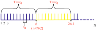
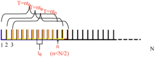
is created, each group becomes a cluster as shown in
Figure 1.
The number of clusters is

.
Figure 1. Data Structure Diagram in AVAR Guidance.
The modified environment of the overlapping AVAR, which is shown in
Figure 2.
In this environment, clusters are overlapped with previous clusters in order to use the data set exhaustively.
Figure 2. Data Structure Used for the Derivation of the Overlapping.
Therefore, the analytical review to be performed is valid for both variances.
There is a period

associated with each cluster, which is equal to


.
If the instantaneous output speed of the inertial sensor is given by

, the group mean value can be calculated using the following equation as in
.
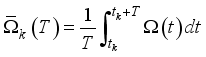 (1)
(1) where

is the average output velocity of the group starting at the

data point, which has

data points.
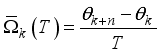
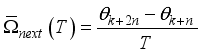
The average value of the next group can be obtained as follows:
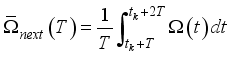 (2)
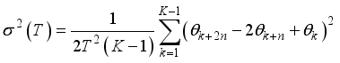
(2) The length k calculated from two neighboring clusters is (IEEE Std 952-1997):
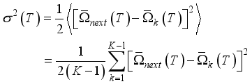 (3)
(3) where

denotes the ensemble mean.
By choosing different cluster lengths or correlation times for each calculation of AVAR, we can obtain as a function of correlation time.
In the log-log plot, this method can distinguish different parts of the errors by checking the gradient of variation of the error.
This is typically plotted with

against the square root of AVAR.
A different random process causes the gradient to occur.
That is, each has an intrinsic gradient and usually appears at different positions in the curve, which makes it possible to distinguish in a straightforward way.
This directly makes it possible for distinguish errors from several random process. This makes it possible to establish a relationship between AVAR and the two adjacent velocity noises PSD.
This is a common method for representing spectral resolution of time series, which is a powerful tool for analyzing data from a random model.
If the attribute values of the correlation time are chosen, information about the angular random walk, quantization noise, bias instability, etc. can be found.
The relationship between PSD

and covariance

can be expressed as
| [6] | Yong Gil Ri, Chol Myong Sin, Jun Gol Kang, Statistical modelling of rate gyros based on fully overlapping Allan variance IET Sci. Meas. Technol. 2021,
https://doi.org/10.1049/smt2.12080 |
[6]
:
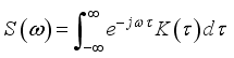 (4)
(4) AVAR can be defined in terms of the exit angle or velocity
:
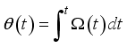 (5)
(5) The integral lower bound is not expressed here because only the angular or velocity differences are used in the definition.
Angle or velocity measurements are performed at a discrete time given by
.
We simplify the notation to

.
The group mean can be written as
 (6)
(6)  (7)
(7) So, AVAR is same as follows.
 (8)
(8) The equivalence relation between Eq. (
8) and can be obtained as
| [6] | Yong Gil Ri, Chol Myong Sin, Jun Gol Kang, Statistical modelling of rate gyros based on fully overlapping Allan variance IET Sci. Meas. Technol. 2021,
https://doi.org/10.1049/smt2.12080 |
[6]
:
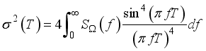 (9)
(9) where

is PSD in the process

, which is assumed to be stationary at that time.
Eq. (
9) is the focus of the AVAR method.
This equation can be used to calculate AVAR from velocity noise PSD.
Any physically meaningful random process PSD can be substituted into an integral, and the expression

for AVAR as a function of the cluster length is established.
On the contrary, since

is a measurable quantity, the log-log plot of

gives a direct representation of the types of random processes present in the inertial sensor data.
The corresponding AVAR of a random process can be uniquely derived from its PSD
.
Table 1. Some Representation from AVAR.
Error sources | AVAR description | gradient |
Quantization error | 
| -1 |
Angle (velocity) random walk | 
| -0.5 |
Bias instability | 
| 0 |
Rate random walk | 
| 0.5 |
Rate Ramp noise | 
| 1 |
Eq. (
10) shows that the total variance of random process using AVAR.
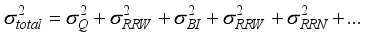 (10)
(10) AVAR is a very effective method to separate the error components at the gyro output according to their own slope in the log-log plot.
Let’s consider about the accuracy of Allan’s variance method and variable-time Allan’s variance method.
Finite number of clusters can generate any finite data set.
AVAR of any noise term is estimated using the total number of clusters with a given length that can be created.
On the contrary, for a given

, the estimation accuracy of AVAR depends on the number of independent clusters within the data set
| [4] | Naser El-Sheimy, Haiying Hou, and Xiaoji Niu, Analysis and Modeling of Inertial Sensors Using Allan Variance, IEEE Transaction on Instrumentation and Measurement, vol. 57, No. 1, 2008, https://doi.org/10.1109/TIM.2007.908635 |
[4]
.
The accuracy in the estimation of

increases with the number of clusters.
In general, we call the percentage error

of the calculation for the

clusters, while computing

.
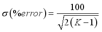 (11)
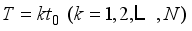
(11) The number of clusters

is given by

, where

is the length of the data set and is the number of points

contained in the cluster.
In the short (long) region

, the estimation error is small (large) because the number of independent clusters in this region is large (small).
This equation can be used to design tests that observe the individual noise of a certain characteristic quantity with a given accuracy, as described in
| [4] | Naser El-Sheimy, Haiying Hou, and Xiaoji Niu, Analysis and Modeling of Inertial Sensors Using Allan Variance, IEEE Transaction on Instrumentation and Measurement, vol. 57, No. 1, 2008, https://doi.org/10.1109/TIM.2007.908635 |
[4]
.
As mentioned above, the number of clusters in the Allan analysis of variance has a direct effect on the estimation accuracy.
On the other hand, AVAR is a method of separating the error components at the gyro output according to their own slope in a log-log plot.
The data density in this log-log plot is shown in the figure.
Thus, the lower the number of data in the cluster in the previous part of the data sequence, the more accurate the data in the cluster in the latter part.
Hence, variable-time Allan analysis has been proposed and the calculation speed can be increased by significantly reducing the number of clusters
. From the nature of the log-log plot, as the AVAR is distributed along the logarithmic scale, the number of data contained in the cluster should be increased geometrically.
In other words, in the time domain, the size of the cluster must increase geometrically.
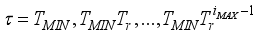 (12)
(12) Here,

is the equivalence value and

is the size in the time domain represented by the cluster from the accuracy constraint.
For an estimation accuracy of 25% from Eq. (
11), the minimum number of clusters is K = 9 if the number of data is n = 3240,000.
In this case, the maximum data score of the cluster is 360,000, and the number of clusters under the lamp ratio is IMAX = 18.
Let’s combine the overlapping AVAR method and the variable-time AVAR method.
The main idea of the overlapping AVAR method is to improve the estimation accuracy by taking the overlapping mean, while in the variable-time AVAR method, it is essential to change the size of the cluster significantly as the density of the data increases in the log-log plot with time.
The key to combining the idea of the overlapping AVAR method with the idea of the variable-time AVAR method is to increase the number of overlapping geometrically (the data structure diagram used in the variable-time overlapping AVAR method). For example, in proposal literature when minimum cluster number is K=9, it can only provide 25% estimation accuracy but with overlapping method when data points are n=324000, it can provide 0.04%estimation accuracy from Eq. (
10).
In contrast in this paper calculation amount decrease 90000 times than proposal overlapping method, i.e. it makes averaging time long exponentially, calculation amount decreases exponentially when data points gets bigger.
3. Denoising
After estimating the type and parameters of noise present in the sensor, noise cancellation should be performed.
In digital signal processing, there are several ways to reduce the noise present in the signal, typically discrete wavelet transformation and median filtering.
These two methods completely eliminate or effectively suppress the noise based on the parameters estimated by the AVAR method.
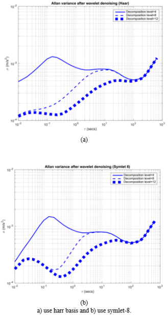
Wavelet denoising is performed through a MATLAB wavelet toolbox.
The order of the wavelet transform can be determined by trial and error as follows.
The basis of the wavelet toolbox is harr basis and symlet8 basis, and the results of 4th, 8th and 12th order wavelet transforms that only the high-frequency noise components are removed in 4th and 8th order wavelet transforms and only the high-frequency and low-frequency components are effectively reduced in the 12th order wavelet transforms.
Figure 3. shows that the filtered result with several basis in case of various decomposition level.
Therefore, using the noise parameters estimated by the AVAR method through the 12th-order wavelet transform with harr and symlet-8 basis, the noise can be effectively eliminated or its influence is sufficiently small.
Therefore, using the noise parameters estimated by the AVAR method through the 12th-order wavelet transform with harr and symlet-8 basis, the noise can be effectively eliminated or its influence is sufficiently small.
As mentioned above, the median filtering process is applied in the denoising step.
Median filtering is a simple structured filtering method that substitutes a measurement with the mean values of neighboring measurements.
Therefore, the resulting signal is directly related to the parameter N, whether N means.
However, as mentioned in
| [8] | Leslie Barreda Pupo, Characterization of Errors and Noises in MEMS Inertial Sensors Using Allan Variance Method [M], Barcelona, 2016. |
[8]
, as N increases, the computational burden increases and the result also decreases significantly compared to wavelet filtering.
Thus, when the median filtering and wavelet excitation are applied together, we can effectively suppress the noise of the field.
Figure 3. Wavelet Denosing.
4. Experiments Setup
Experimental conditions: MPU9250 Inertial Sensor Number of Experiments: 3.
Experimental times: 30min, 1 h, 1 h and 30 min.
Sampling times: 10 ms, 4 ms and 10 ms.
The IMU that was used in the experiment is MPU9250 IMU in which 3-axis accelerometer, 3-axis gyro are embedded. For the data acquisition, an experimental setup was held in a customized desk at room temperature for several days. The experimental setup is involved: a modified IMU model MPU9250, a laptop model Dell XPS M1330 with operating systems Windows7 64bit-Ultimate, and a C++ driver to extract the data from the sensor.
The modified IMU MPU9250 is a high-performance, miniature IMU using MEMS sensor technology. It combines a tri-axial accelerometer, a tri-axial gyro, temperature sensors, and an on-board processor, running a sophisticated sensor fusion algorithm to provide static and dynamic orientation and inertial measurements.
The laptop is a 64-bits ASUS S301LP with CPU Intel Core i7-4500U at 1.8 GHz (4CPUs) ~2.4GHz with Data Bus Speed of 1300 MHz.
MPU 9250 IMU has been setup in a duralumin box and in I2C mode collected the sensor data.
The main processor is STM32F407.
To remove the drift according to the temperature change we first designed a thermostat.
Micro-controller processes the measurements from the IMU and sends the result to the host computer through USB-232 converter.
The host computer performs calibration using these measurements.
The sensor data is obtained in zero positions for 0min, 1 h, 1 h and 30 min. Sampling period is 15ms and measuring range is set to

.
5. Experiments and Results
Following
Figures 4, 5 shows that the result of data denoised with modified AVAR.
In general, using AVAR of data we can get noise characteristics and perform denosing process.
But AVAR method needs high calculation amount in case of high accuracy or low accuracy with less calculation amount.
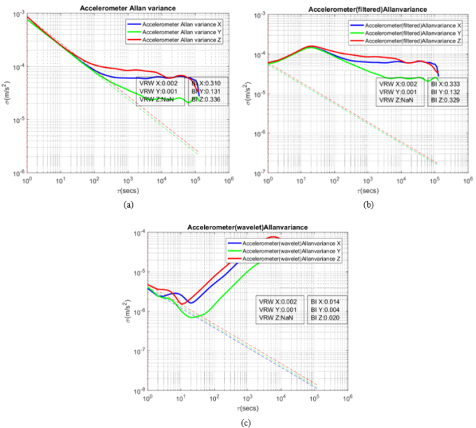
Table 2. Estimation Result of Accelerometer Using AVAR After Denosing.
Error source | No-filter | Median-filter | Wavelet-filter |
BI | x | 0.310 | 0.333 | 0.014 |
y | 0.131 | 0.132 | 0.004 |
z | 0.336 | 0.329 | 0.020 |
VRW | x | 0.002 | 0.002 | 0.002 |
y | 0.001 | 0.001 | 0.001 |
z | NaN | NaN | NaN |
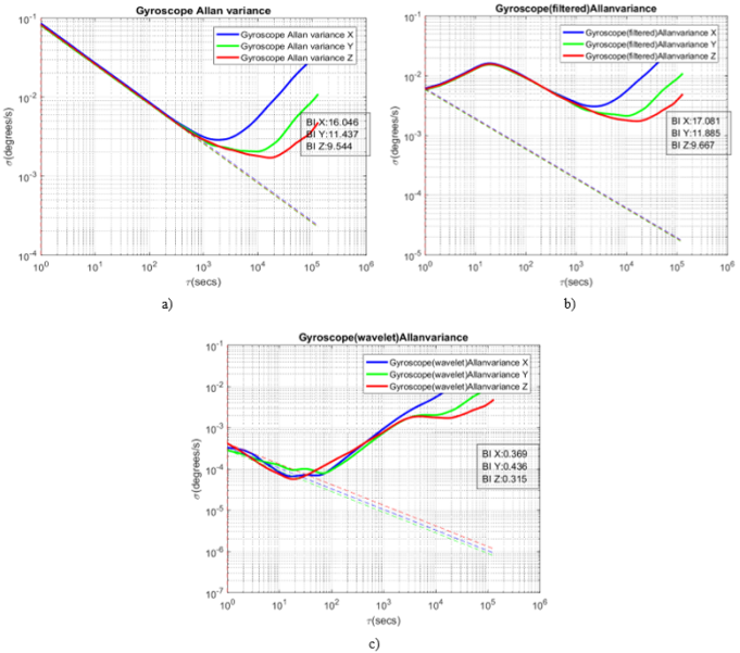
Table 3. Estimation Result of Gyroscope Using AVAR After Denosing.
Error source | No-filter | Median-filter | Wavelet-filter |
BI | x | 16.046 | 17.061 | 0.369 |
y | 11.437 | 11.885 | 0.436 |
z | 9.544 | 9.667 | 0.315 |
For overcoming this problem, we can use modified AVAR method.
In
Figures 4, 5, a) shows that AVAR of original data, b) shows result from median filtered data and c) shows result from wavelet denoised data.
As you can see from
Tables 2, 3 the suggested modified AVAR method accurately reflects the noise characteristics from denoised data as compared with original data, i.e. combining time controllable method and overlapping method, the accuracy radically improved from 25% to 0.04% but also calculation amount decreased 90000 times when N=3240000.
Figure 4. AVAR of Accelerometers.
a) from original data b) from median filtered data c) from wavelet denoised data.
6. Conclusions
In the paper we described the modified AVAR which can overcome calculation problem and accuracy problem simultaneously in MEMS accelerometer and gyroscope.
Using this algorithm, we verified that noise term: bias instability and velocity random walk effectively reduced with various filter in view of modified AVAR.
This result shows that this modified AVAR method this paper suggested accurately reflects the noise characteristics.
Figure 5. AVAR of Accelerometers.
a) from original data b) from median filtered data c) from wavelet denoised data.
We proved the effectiveness of this algorithm using the measurements of MPU 9250 IMU in the stationary position.
This method can be used in various low-cost IMU.
If the accelerometers, gyros errors are characterized using this approach, the computation accuracy and computation amount are greatly improved in navigation system.
Abbreviations
AVAR | Allan Variance |
IMU | Inertial Measurement Unit |
INS | Inertial Navigation System |
MEMS | Micro Electro Mechanical System |
PSD | Power Spectral Density |
KF | Kalman Filter |
UAV | Unmanned Aircraft Vehicle |
UGV | Unmanned Ground Vehicle |
Conflicts of Interest
The authors declare no conflicts of interest.
References
| [1] |
M. R. Emami Shaker, A. Ghaffari, A. Maghsoodpour, A. Khodayari, GPS/INS Integration for Vehicle Navigation based on INS Error Analysis in Kalman Filtering, International Journal of Automotive Engineering, Vol. 6, No. 4, pp. 2562-2570, 2017,
https://doi.org/10.22068/ijae.7.4.2562
|
| [2] |
Hao Peng and Xiaoli Bai, Machine Learning Gyro Calibration Method Based on Attitude Estimation, JOURNAL OF SPACECRAFT AND ROCKETS, Vol. 58, No. 6, 2021,
https://doi.org/10.2514/1.A34979
|
| [3] |
Gökçen Aslan Aydemir and Afsar Saranli, Characterization and calibration of MEMS inertial sensors for state and parameter estimation applications, Measurement, Vol. 45, pp. 1210-1225, 2012,
https://doi.org/10.1016/j.measurement.2012.01.015
|
| [4] |
Naser El-Sheimy, Haiying Hou, and Xiaoji Niu, Analysis and Modeling of Inertial Sensors Using Allan Variance, IEEE Transaction on Instrumentation and Measurement, vol. 57, No. 1, 2008,
https://doi.org/10.1109/TIM.2007.908635
|
| [5] |
Hong yu Zhao and Zhe long Wang, A time-controllable Allan variance method for MEMS IMU, An International Journal, 40/2 pp. 111–120, 2013,
https://doi.org/10.1108/01439911311297702
|
| [6] |
Yong Gil Ri, Chol Myong Sin, Jun Gol Kang, Statistical modelling of rate gyros based on fully overlapping Allan variance IET Sci. Meas. Technol. 2021,
https://doi.org/10.1049/smt2.12080
|
| [7] |
L. Wang, C. Zhang, T. Lin, X. li, T. Wang, Characterization of a Fiber Optic Gyroscope in a Measurement While Drilling System with the Dynamic Allan Variance, Measurement, pp. 1-18, 2015,
https://doi.org/10.1016/j.measurement.2015.05.001
|
| [8] |
Leslie Barreda Pupo, Characterization of Errors and Noises in MEMS Inertial Sensors Using Allan Variance Method [M], Barcelona, 2016.
|
| [9] |
Martin Sipos, Improvement of inertial navigation system accuracy using alternative sensors [D], Czech Technical University In Prague, 2015.
|
| [10] |
Zhang Xiaoming, Chen Guobin, Li Jie and Liu Jun, Calibration of triaxial MEMS vector field measurement system, IET Science, Measurement and Technology, Vol. 8, Iss. 6, pp. 601–609, 2013,
https://doi.org/10.1049/iet-smt.2013.0202
|
| [11] |
Sok Hun Kim, Bong Il Kim and Thae Ju Ri, Controlling and Management of the MEMS IMU's temperature with a Peltier Plate, Journal of Thermal Engineering and Applications, Vol 10, pp. 36-45, 2024,
https://doi.org/10.37591/JoTEA
|
| [12] |
Quan Zhang, Xiaoji Niu, Chuang Shi, Assessment of the effect of GNSS sampling rate on GNSS-INS relative accuracy on different time scales for precision measurements, Measurement, pp. 583-593, 2019,
https://doi.org/10.1016/j.measurement.2019.05.104
|
| [13] |
Liangxin Yuan, Yuan Wang, Peng Du and Xiaomin Lian, Improve the accuracy of vehicle velocity estimation based on low-cost GPS/IMU by GPS course angle, Journal of Automobile Engineering, Vol. 237(8). pp. 1975-1993, 2023,
https://doi.org/10.1177/09544070221103172
|
| [14] |
Zhihuang Zhang, Jintao Zhao, Changyao Huang and Liang Li, Precise and robust sideslip angle estimation based on INS/GNSS integration using invariant extended Kalman filter, Journal of Automobile Engineering, Vol. 237(8). pp. 1805-1818, 2023,
https://doi.org/10.1177/09544070221102662
|
| [15] |
Xin Nie, Jun Gong 1, Jintao Cheng, Xiaoyu Tang and Yuanfang Zhang, Two-Step Self-Calibration of LiDAR-GPS/IMU Based on Hand-Eye Method, Symmetry, pp. 1-15, 2023,
https://doi.org/10.3390/sym15020254
|
| [16] |
Zixuan Zheng, Sha Wang, Baichun Gong, Erlong Su and Hefei Huang, Study on angle-only relative navigation for unmanned aerial vehicle formation in GPS-denied environment, Journal of Aerospace Engineering, Vol. 237(10). pp. 2252-2265, 2023,
https://doi.org/10.1177/09544100221149235
|
Cite This Article
-
APA Style
Kim, S. H., Kim, Y. S., Pak, J. H., Ri, S. I., Han, I. G. (2026). Characterization Method for Errors of Inertial Sensor Using Improved Allan Variance Algorithm. American Journal of Robotics and Intelligent Systems, 1(1), 38-45. https://doi.org/10.11648/j.ajris.20260101.15
 Copy
|
Copy
|
 Download
ACS Style
Kim, S. H.; Kim, Y. S.; Pak, J. H.; Ri, S. I.; Han, I. G. Characterization Method for Errors of Inertial Sensor Using Improved Allan Variance Algorithm. Am. J. Rob. Intell. Syst. 2026, 1(1), 38-45. doi: 10.11648/j.ajris.20260101.15
Copy
|
Download
AMA Style
Kim SH, Kim YS, Pak JH, Ri SI, Han IG. Characterization Method for Errors of Inertial Sensor Using Improved Allan Variance Algorithm. Am J Rob Intell Syst. 2026;1(1):38-45. doi: 10.11648/j.ajris.20260101.15
Copy
|
Download
-
@article{10.11648/j.ajris.20260101.15,
  author = {Sok Hun Kim and Yun Song Kim and Jin Hyang Pak and Sung Il Ri and Il Gwang Han},
  title = {Characterization Method for Errors of Inertial Sensor Using Improved Allan Variance Algorithm},
  journal = {American Journal of Robotics and Intelligent Systems},
  volume = {1},
  number = {1},
  pages = {38-45},
  doi = {10.11648/j.ajris.20260101.15},
  url = {https://doi.org/10.11648/j.ajris.20260101.15},
  eprint = {https://article.sciencepublishinggroup.com/pdf/10.11648.j.ajris.20260101.15},
  abstract = {The Inertial Navigation System (INS) can provide position, velocity and attitude information with high accuracy with a short time period. In recent years, due to its small size, light weight, low consumption of electricity, and low cost, micro-electromechanical systems (MEMS), IMUs (Inertial Measurement Units) have been increasingly popular in robotics, Unmanned Aircraft Vehicles (UAVs), and Unmanned Ground Vehicles (UGVs). MEMS IMUs combine a 3-axis accelerometer, 3-axis gyroscope, 3-axis magnetometer, thermometer, and other components into a single microchip; nevertheless, the accuracy of MEMS IMU is sometimes poor, especially, the accuracy of these information decreases rapidly with time. To accurately estimate the navigation information, it is necessary to characterize the error components of the sensors. In this paper, we present a method which can simultaneously increase the computational accuracy and computational speed of Allan variance (AVAR) method with combining the variable-time averaging method with the overlapping AVAR method, in order to take advantage of the improvement methods of AVAR proposed in the literature and overcome the shortcomings. We also present an efficient noise reduction method and verified the efficiency with parameters estimated using the AVAR method. We proved the effectiveness of this algorithm using the raw data of MPU9250 in the static position. The experimental result shows that the improved AVAR approach combining variable-time method and overlapping method is better than the others.},
 year = {2026}
}
Copy
|
Download
-
TY  - JOUR
T1  - Characterization Method for Errors of Inertial Sensor Using Improved Allan Variance Algorithm
AU  - Sok Hun Kim
AU  - Yun Song Kim
AU  - Jin Hyang Pak
AU  - Sung Il Ri
AU  - Il Gwang Han
Y1  - 2026/03/12
PY  - 2026
N1  - https://doi.org/10.11648/j.ajris.20260101.15
DO  - 10.11648/j.ajris.20260101.15
T2  - American Journal of Robotics and Intelligent Systems
JF  - American Journal of Robotics and Intelligent Systems
JO  - American Journal of Robotics and Intelligent Systems
SP  - 38
EP  - 45
PB  - Science Publishing Group
UR  - https://doi.org/10.11648/j.ajris.20260101.15
AB  - The Inertial Navigation System (INS) can provide position, velocity and attitude information with high accuracy with a short time period. In recent years, due to its small size, light weight, low consumption of electricity, and low cost, micro-electromechanical systems (MEMS), IMUs (Inertial Measurement Units) have been increasingly popular in robotics, Unmanned Aircraft Vehicles (UAVs), and Unmanned Ground Vehicles (UGVs). MEMS IMUs combine a 3-axis accelerometer, 3-axis gyroscope, 3-axis magnetometer, thermometer, and other components into a single microchip; nevertheless, the accuracy of MEMS IMU is sometimes poor, especially, the accuracy of these information decreases rapidly with time. To accurately estimate the navigation information, it is necessary to characterize the error components of the sensors. In this paper, we present a method which can simultaneously increase the computational accuracy and computational speed of Allan variance (AVAR) method with combining the variable-time averaging method with the overlapping AVAR method, in order to take advantage of the improvement methods of AVAR proposed in the literature and overcome the shortcomings. We also present an efficient noise reduction method and verified the efficiency with parameters estimated using the AVAR method. We proved the effectiveness of this algorithm using the raw data of MPU9250 in the static position. The experimental result shows that the improved AVAR approach combining variable-time method and overlapping method is better than the others.
VL  - 1
IS  - 1
ER  -
Copy
|
Download