The increasing demand for sustainable electricity generation necessitates the exploration of innovative technologies. Biomass technology is emerging as a promising alternative to address the energy crisis for low-power devices and reduce reliance on fossil fuels. One of the methods to generate energy from this biomass is by using microbial fuel cells (MFC). However, the efforts made with this technology are still mainly limited at the laboratory scale, limiting its interest and its utilization for electrical power generation. This paper presents the real-life implementation and feasibility of a dual-chamber microbial fuel cell fabricated with concrete. 15 dual-chamber reactors were manufactured, with a volume of 0.5 liters for each chamber. Inside the anodic chamber, a carbon foam measuring 4.5 x 4.5 cm² was placed and used as the anode electrode. Two different electrode materials were used for the cathode electrodes. Six reactors used 4.5 x 4.5 cm2 carbon foam while the other 9 used graphite rods of 5 mm diameter and 15 cm long. The anode chamber was inoculated with a mixture of 25% cow dung and 75% tap water and then sealed airtight. Each cathode chamber was filled with 0.5 liters of saline solution. After 7 days of manipulation, the Open Circuit Voltage (OCV) obtained from this investigation ranged from 0.415 V to 0.732 V. That reflects the successful conversion of chemical energy of this waste in the concrete-based microbial fuel cell reactor into electrical energy. The average maximum power density obtained using graphite rod cathodes was 14.15 mW/m² while an average of 20.21 mW/m² was obtained from the MFCs using carbon foam cathodes. When the MFCs were stacked together in series, a total voltage of 8.5 V was observed.
| Published in | American Journal of Electrical Power and Energy Systems (Volume 14, Issue 1) |
| DOI | 10.11648/j.epes.20251401.12 |
| Page(s) | 11-19 |
| Creative Commons |
This is an Open Access article, distributed under the terms of the Creative Commons Attribution 4.0 International License (http://creativecommons.org/licenses/by/4.0/), which permits unrestricted use, distribution and reproduction in any medium or format, provided the original work is properly cited. |
| Copyright |
Copyright © The Author(s), 2025. Published by Science Publishing Group |
Dual Chamber Microbial Fuel Cell, Cow Dung, Concrete-Based Reactor, Electrical Energy Harvesting
Design | Characteristics |
|---|---|
Reactor type | concrete material |
Structure type | two-chamber MFC |
Internal volume | 0.5 liters for each chamber |
Reactor thickness | 2.5 cm |
Inlet and outlet hole | 2.5 cm in diameter |
Anode electrode | 4.5 x 4.5 cm² carbon foam material. |
Cathode electrode | 4.5 x 4.5 cm² carbon foam and 5 mm diameter, 15 cm long graphite rod. |
PEM | Agar in 3.1 cm long and 2.5 cm diameter PVC pipe |
Inoculum/Substrate | 25% cow dung mixed with 75% tap water |
Current collector | stainless steel 0.6 mm in diameter |
Gas pipe | a 5 mm outer diameter pipe |
Cell N° | Cathode electrode | Initial residue OCV(V) | Final stable OCV(V) |
|---|---|---|---|
1 | Graphite rod | 0.073 | 0.731 |
2 | Graphite rod | 0.067 | 0.506 |
3 | Graphite rod | 0.156 | 0.708 |
4 | Graphite rod | 0.142 | 0.641 |
5 | Carbone foam | 0.070 | 0.430 |
6 | Carbone foam | 0.071 | 0.415 |
7 | Graphite rod | 0.049 | 0.510 |
8 | Carbone foam | 0.085 | 0.500 |
9 | Carbone foam | 0.037 | 0.535 |
10 | Graphite rod | 0.082 | 0.618 |
11 | Carbone foam | 0.150 | 0.650 |
12 | Graphite rod | 0.080 | 0.718 |
13 | Carbone foam | 0.073 | 0.487 |
14 | Graphite rod | 0.053 | 0.600 |
15 | Graphite rod | 0.056 | 0.481 |
MFC Reactor Design | Electrodes | Power (mW/m2) | Ref. |
|---|---|---|---|
acrylic resin single Chamber | Plain graphite anode, air cathode With Nafion PEM | 0.34 | [26] |
acrylic plate single Chamber | Carbone fiber brush anode, Roll-pressing air cathode with conductive graphite | 1.734 | [27] |
PLA single chamber | Carbon foam anode, air cathode with Nafion PEM | 14.1 | [28] |
PVC bottles double chamber | Copper rods with agarose PEM | 9.47E-04 | [29] |
Plastic containers double chamber | Graphite rod, Lamp wicks PEM | 6E-04 | [30] |
Concrete-based dual-chamber | Carbon foam anode and cathode with agar PEM | 20.21 | This work |
Carbon foam anode and graphite rod cathode with agarose | 14.15 |
MFC | Microbial Fuel Cell |
PEM | Proton Exchange Membrane |
PVC | Poly Vinyl Chloride |
CAD | Computer-Aided Design |
OCV | Open Circuit Voltage |
| [1] |
Bulletin, E. Peak People: The Interrelationship between Population Growth and Energy Resources Available online:
https://www.resilience.org/stories/2009-04-20/peak-people-interrelationship-between-population-growth-and-energy-resources/ (accessed on 8 September 2024). |
| [2] | Mombekova, G.; Nurgabylov, M.; Baimbetova, A.; Keneshbayev, B.; Izatullayeva, B. The Relationship Between Energy Consumption, Population and Economic Growth in Developing Countries. International Journal of Energy Economics and Policy 2024, 14, 368–374, |
| [3] | Ritchie, H.; Rosado, P.; Roser, M. Energy Production and Consumption. Our World in Data 2024. |
| [4] | Flimban, S. G. A.; Kim, T.; Ismail, I. M. I.; Oh, S.-E. Overview of Microbial Fuel Cell (MFC) Recent Advancement from Fundamentals to Applications: MFC Designs, Major Elements, and Scalability 2018. |
| [5] | Li, W.-W.; Yu, H.-Q.; He, Z. Towards Sustainable Wastewater Treatment by Using Microbial Fuel Cells-Centered Technologies. Energy Environ. Sci. 2013, 7, 911–924, |
| [6] | Du, Z.; Li, H.; Gu, T. A State of the Art Review on Microbial Fuel Cells: A Promising Technology for Wastewater Treatment and Bioenergy. Biotechnology Advances 2007, 25, 464–482, |
| [7] | Logan, B. E.; Rabaey, K. Conversion of Wastes into Bioelectricity and Chemicals by Using Microbial Electrochemical Technologies. Science 2012, 337, 686–690, |
| [8] | Kouam Ida, T.; Mandal, B. Microbial Fuel Cell Design, Application and Performance: A Review. Materials Today: Proceedings 2023, 76, 88–94, |
| [9] | Logan, B. E.; Hamelers, B.; Rozendal, R.; Schröder, U.; Keller, J.; Freguia, S.; Aelterman, P.; Verstraete, W.; Rabaey, K. Microbial Fuel Cells: Methodology and Technology. Environ. Sci. Technol. 2006, 40, 5181–5192, |
| [10] | Potter, M. C.; Waller, A. D. Electrical Effects Accompanying the Decomposition of Organic Compounds. Proceedings of the Royal Society of London. Series B, Containing Papers of a Biological Character 1997, 84, 260–276, |
| [11] | Liu, H.; Logan, B. E. Electricity Generation Using an Air-Cathode Single Chamber Microbial Fuel Cell in the Presence and Absence of a Proton Exchange Membrane. Environ. Sci. Technol. 2004, 38, 4040–4046, |
| [12] | Włodarczyk, B.; Włodarczyk, P. P.; Kalinichenko, A. Single Chamber Microbial Fuel Cell with Ni-Co Cathode. 2017, 19, 01025, |
| [13] | Uma Vanitha, M.; Natarajan, M.; Sridhar, H.; Umamaheswari, S. Microbial Fuel Cell Characterisation and Evaluation of Lysinibacillus Macroides MFC02 Electrigenic Capability. World J Microbiol Biotechnol 2017, 33, 91, |
| [14] | Ieropoulos, I.; Greenman, J.; Melhuish, C. Microbial Fuel Cells Based on Carbon Veil Electrodes: Stack Configuration and Scalability. Int. J. Energy Res. 2008, 32, 1228–1240, |
| [15] | Ieropoulos, I. A.; Greenman, J.; Melhuish, C. Miniature Microbial Fuel Cells and Stacks for Urine Utilisation. International Journal of Hydrogen Energy 2013, 38, 492–496, |
| [16] | Aelterman, P.; Rabaey, K.; Pham, H. T.; Boon, N.; Verstraete, W. Continuous Electricity Generation at High Voltages and Currents Using Stacked Microbial Fuel Cells. Environ. Sci. Technol. 2006, 40, 3388–3394, |
| [17] | Gil, G.-C.; Chang, I.-S.; Kim, B.-H.; Kim, M.; Jang, J.-K.; Park, H. S.; Kim, H.-J. Operational Parameters Affecting the Performannce of a Mediator-Less Microbial Fuel Cell. Biosens Bioelectron 2003, 18, 327–334, |
| [18] | Hisham, S.; ZAIN, S.; JUSOH, S.; Anuar, N.; Suja, F.; Ismail, A.; BASRI, N. Microbial Fuel Cells Using Different Types of Wastewater for Electricity Generation and Simultaneously Removed Pollutant. Journal of Engineering Science and Technology 2013, 8, 317–326. |
| [19] | Cheng, S.; Logan, B. E. Increasing Power Generation for Scaling up Single-Chamber Air Cathode Microbial Fuel Cells. Bioresource Technology 2011, 102, 4468–4473, |
| [20] | Feng, Y.; Wang, X.; Logan, B. E.; Lee, H. Brewery Wastewater Treatment Using Air-Cathode Microbial Fuel Cells. Appl Microbiol Biotechnol 2008, 78, 873–880, |
| [21] | Nam, J.-Y.; Kim, H.-W.; Lim, K.-H.; Shin, H.-S.; Logan, B. E. Variation of Power Generation at Different Buffer Types and Conductivities in Single Chamber Microbial Fuel Cells. Biosens Bioelectron 2010, 25, 1155–1159, |
| [22] | Behera, M.; Murthy, S. S. R.; Ghangrekar, M. M. Effect of Operating Temperature on Performance of Microbial Fuel Cell. Water Science and Technology 2011, 64, 917–922, |
| [23] | Khaled, F. Contribution to electrical valorization of microbial fuel cells, 2016. |
| [24] | Larrosa-Guerrero, A.; Scott, K.; Head, I. M.; Mateo, F.; Ginesta, A.; Godinez, C. Effect of Temperature on the Performance of Microbial Fuel Cells. Fuel 2010, 89, 3985–3994, |
| [25] | Song, Y.; An, J.; Chae, K.-J. Effect of Temperature Variation on the Performance of Microbial Fuel Cells. Energy Technology 2017, 5, 2163–2167, |
| [26] | Yokoyama, H.; Ohmori, H.; Ishida, M.; Waki, M.; Tanaka, Y. Treatment of Cow-Waste Slurry by a Microbial Fuel Cell and the Properties of the Treated Slurry as a Liquid Manure. Animal Sci J 2006, 77, 634–638, |
| [27] | Liu, J. H.; Chen, D.; Mahmood, A.; Yang, S. J. STUDY ON THE SYNERGISTIC EFFECT OF MICROBIAL FUEL CELL ON THE TREATMENT OF LIVESTOCK AND POULTRY MANURE SLURRY. Appl. Ecol. Env. Res. 2024, 22, 3797–3813, |
| [28] | Douma, M. N. K.; Ondel, O.; Tsafack, P.; Mieyeville, F.; Kengnou, N. A. Microbial Fuel Cell: Investigation of the Electrical Power Production of Cow Dung and Human Faeces Using 3D-Printed Reactors. Bioresource Technology Reports 2025, 29, 102036, |
| [29] | Parkash, A. Characterization of Generated Voltage, Current, Power and Power Density from Cow Dung Using Double Chambered Microbial Fuel Cell. J Phys Chem Biophys 2016, 6, |
| [30] | Kamau J. M; Mbui D. N; Mwaniki J. M; Mwaura F. B Cow Dung to Kilo Watt Using Double Chamber Microbial Fuel Cell. 2017. |
| [31] | An, J.; Sim, J.; Lee, H.-S. Control of Voltage Reversal in Serially Stacked Microbial Fuel Cells through Manipulating Current: Significance of Critical Current Density. Journal of Power Sources 2015, 283, 19–23, |
| [32] | An, J.; Kim, B.; Chang, I. S.; Lee, H.-S. Shift of Voltage Reversal in Stacked Microbial Fuel Cells. Journal of Power Sources 2015, 278, 534–539, |
| [33] | Oh, S.-E.; Logan, B. E. Voltage Reversal during Microbial Fuel Cell Stack Operation. Journal of Power Sources 2007, 167, 11–17, |
APA Style
Douma, M. N. K., Katche, M. L., Telem, N. A. K., Ayuk, A. N. V., Tsafack, P., et al. (2025). Concrete-Based Dual-Chamber Microbial Fuel Cell for Continuous Power Generation. American Journal of Electrical Power and Energy Systems, 14(1), 11-19. https://doi.org/10.11648/j.epes.20251401.12
ACS Style
Douma, M. N. K.; Katche, M. L.; Telem, N. A. K.; Ayuk, A. N. V.; Tsafack, P., et al. Concrete-Based Dual-Chamber Microbial Fuel Cell for Continuous Power Generation. Am. J. Electr. Power Energy Syst. 2025, 14(1), 11-19. doi: 10.11648/j.epes.20251401.12
@article{10.11648/j.epes.20251401.12,
  author = {Marie Norbertine Kamdjou Douma and Musong Louis Katche and Nicole Adelaïde Kengnou Telem and Ayuk Ngang Valdo Ayuk and Pierre Tsafack and Olivier Ondel and Fabien Mieyeville},
  title = {Concrete-Based Dual-Chamber Microbial Fuel Cell for Continuous Power Generation
},
  journal = {American Journal of Electrical Power and Energy Systems},
  volume = {14},
  number = {1},
  pages = {11-19},
  doi = {10.11648/j.epes.20251401.12},
  url = {https://doi.org/10.11648/j.epes.20251401.12},
  eprint = {https://article.sciencepublishinggroup.com/pdf/10.11648.j.epes.20251401.12},
  abstract = {The increasing demand for sustainable electricity generation necessitates the exploration of innovative technologies. Biomass technology is emerging as a promising alternative to address the energy crisis for low-power devices and reduce reliance on fossil fuels. One of the methods to generate energy from this biomass is by using microbial fuel cells (MFC). However, the efforts made with this technology are still mainly limited at the laboratory scale, limiting its interest and its utilization for electrical power generation. This paper presents the real-life implementation and feasibility of a dual-chamber microbial fuel cell fabricated with concrete. 15 dual-chamber reactors were manufactured, with a volume of 0.5 liters for each chamber. Inside the anodic chamber, a carbon foam measuring 4.5 x 4.5 cm² was placed and used as the anode electrode. Two different electrode materials were used for the cathode electrodes. Six reactors used 4.5 x 4.5 cm2 carbon foam while the other 9 used graphite rods of 5 mm diameter and 15 cm long. The anode chamber was inoculated with a mixture of 25% cow dung and 75% tap water and then sealed airtight. Each cathode chamber was filled with 0.5 liters of saline solution. After 7 days of manipulation, the Open Circuit Voltage (OCV) obtained from this investigation ranged from 0.415 V to 0.732 V. That reflects the successful conversion of chemical energy of this waste in the concrete-based microbial fuel cell reactor into electrical energy. The average maximum power density obtained using graphite rod cathodes was 14.15 mW/m² while an average of 20.21 mW/m² was obtained from the MFCs using carbon foam cathodes. When the MFCs were stacked together in series, a total voltage of 8.5 V was observed.
},
 year = {2025}
}
TY  - JOUR
T1  - Concrete-Based Dual-Chamber Microbial Fuel Cell for Continuous Power Generation

AU  - Marie Norbertine Kamdjou Douma
AU  - Musong Louis Katche
AU  - Nicole Adelaïde Kengnou Telem
AU  - Ayuk Ngang Valdo Ayuk
AU  - Pierre Tsafack
AU  - Olivier Ondel
AU  - Fabien Mieyeville
Y1  - 2025/02/17
PY  - 2025
N1  - https://doi.org/10.11648/j.epes.20251401.12
DO  - 10.11648/j.epes.20251401.12
T2  - American Journal of Electrical Power and Energy Systems
JF  - American Journal of Electrical Power and Energy Systems
JO  - American Journal of Electrical Power and Energy Systems
SP  - 11
EP  - 19
PB  - Science Publishing Group
SN  - 2326-9200
UR  - https://doi.org/10.11648/j.epes.20251401.12
AB  - The increasing demand for sustainable electricity generation necessitates the exploration of innovative technologies. Biomass technology is emerging as a promising alternative to address the energy crisis for low-power devices and reduce reliance on fossil fuels. One of the methods to generate energy from this biomass is by using microbial fuel cells (MFC). However, the efforts made with this technology are still mainly limited at the laboratory scale, limiting its interest and its utilization for electrical power generation. This paper presents the real-life implementation and feasibility of a dual-chamber microbial fuel cell fabricated with concrete. 15 dual-chamber reactors were manufactured, with a volume of 0.5 liters for each chamber. Inside the anodic chamber, a carbon foam measuring 4.5 x 4.5 cm² was placed and used as the anode electrode. Two different electrode materials were used for the cathode electrodes. Six reactors used 4.5 x 4.5 cm2 carbon foam while the other 9 used graphite rods of 5 mm diameter and 15 cm long. The anode chamber was inoculated with a mixture of 25% cow dung and 75% tap water and then sealed airtight. Each cathode chamber was filled with 0.5 liters of saline solution. After 7 days of manipulation, the Open Circuit Voltage (OCV) obtained from this investigation ranged from 0.415 V to 0.732 V. That reflects the successful conversion of chemical energy of this waste in the concrete-based microbial fuel cell reactor into electrical energy. The average maximum power density obtained using graphite rod cathodes was 14.15 mW/m² while an average of 20.21 mW/m² was obtained from the MFCs using carbon foam cathodes. When the MFCs were stacked together in series, a total voltage of 8.5 V was observed.

VL  - 14
IS  - 1
ER  -
Department of Electrical and Electronics Engineering, Faculty of Engineering and Technology, University of Buea, Buea, Cameroon; Laboratory of Electrical Engineering and Computing (LEEC), University of Buea, Buea, Cameroon; Department of Electrical Engineering, Claude Bernard University Lyon 1, Villeurbanne, France
Biography: Marie Norbertine Kamdjou Douma is a PhD student under the joint program between the University of Buea (Faculty of Engineering) in Cameroon and the University of Claude Bernard Lyon1 (Department of Electronic, Electrotechnics, and Automatic) in France. She completed her Master of Engineering in power systems in the Department of Electrical and Electronic Engineering in the Faculty of Engineering and Technology of the University of Buea, Cameroon in 2021, and her Master in Physics, from the Faculty of Science of this same University in 2018. Her research interests are Renewable Energy Systems, power systems, and electronics. She had 6 months of learning in renewable energy at the School of Engineering (Department of Renewable Energy) of the University of Zambia, Lusaka, Zambia. She participated several times in the online training offered by RES4Africa Foundation concerning renewable energy and microgrids.
Research Fields: Renewable energy, power systems, microbial fuel cell, microgrids, 3D technologies.

Department of Electrical and Electronics Engineering, Faculty of Engineering and Technology, University of Buea, Buea, Cameroon; Laboratory of Electrical Engineering and Computing (LEEC), University of Buea, Buea, Cameroon
Biography: Musong Louis Katche completed his Ph.D. degrees in Power Systems Engineering and Energy Studies from the University of Buea in Cameroon and Moi University in Kenya respectively in 2023, and his Master of Engineering in Power Systems from the University of Buea in 2017. He is an Instructor in the Department of Electrical and Electronic Engineering, Faculty of Engineering and Technology, University of Buea. Additionally, Musong is a member of the National Order of Electrical Engineers (ONIGE) in Cameroon. He holds a certificate of Excellence from the Florence School of Regulation in Italy for Regulation of SDG 7. He is a certified Energy Transformation Expert by the Renewables Academy (RENAC) based in Germany. His research interests are Renewable Energy Systems, Power Electronics and Control, Power Systems, Microgrids, and Energy systems modeling and policies. He has had a research collaboration visit to the Ampere Laboratory at INSA Lyon in France.
Research Fields: Renewable energy, power systems, power electronics and control, microgrids, Energy policies.

Department of Electrical and Electronics, College of Technology, University of Buea, Buea, Cameroon
Biography: Nicole Adelaide Kengnou Telem completed her PhD degree in electronics in the faculty of Sciences of the University of Dschang, Cameroon. She completed her Master's degree in Electronics in 2012 in the same faculty. She graduated from the Advanced Teacher’s Training College for Technical Education (ENSET) – University of Douala, with DIPET 1 (Bachelor in Electrical and Electronics Engineering) and DIPET 2 respectively in 2003 and 2005. She is currently employed as an Instructor at the University of Buea, Cameroon, within the Electrical and Electronic Department of the College of Technology. Her primary research focus lies in the domain of Biomedical Signal and Image Processing for telemedicine purposes, where she harnesses the potential of chaos systems and Artificial Intelligence (AI) techniques. Machine Learning (ML) and Deep Learning (DL), as integral components of AI, offer valuable tools for enhancing healthcare by assisting medical professionals in patient care and clinical data management.
Research Fields: Applied physics/electronic, Biomedical image and signal processing, machine learning, cryptography and security, Internet of medical things, PV solar system, computer aided diagnosis.
Department of Electrical and Electronics Engineering, Faculty of Engineering and Technology, University of Buea, Buea, Cameroon
Biography: Ayuk Ngang Valdo Ayuk is a recent graduate of the University of Buea, where he earned a Bachelor of Engineering degree in Electrical and Electronic Engineering, with a specialty in Power Systems Engineering. His academic journey has equipped him with a solid foundation in power system design. Ayuk is particularly interested in renewable energy solutions, electronics, electrical machines, and their integration into modern power systems. He has actively participated in projects that focus on enhancing energy efficiency and exploring innovative technolo-gies in the field. Committed to advancing the field of electrical engineering, Ayuk seeks opportunities for collaboration and research in the diverse field of power systems.
Research Fields: Power systems, electronics, renewable energy, artificial intelligence, microgrids.

Department of Electrical and Electronics Engineering, Faculty of Engineering and Technology, University of Buea, Buea, Cameroon; Laboratory of Electrical Engineering and Computing (LEEC), University of Buea, Buea, Cameroon
Biography: Pierre Tsafack is an Associate Professor in Electronic Engineering. He completed his Ph.D. in Applied Electronics under a joint program between the National Advanced School of Engineering (Polytechnic), Cameroon, and “Laboratoire Ampere -Institut National des sciences appliquées de Lyon-France’’ in 2011. He obtained his Master's degree in Electronics from the University of Yaoundé I in Cameroon. He assumed duty as Assistant Lecturer of Electronics Engineering in the Department of Electrical and Electronic Engineering, Faculty of Engineering and Technology, University of Buea in August 2012. Prior to this, he worked as an Instructor in the Department of Electrical and Telecommunications Engineering at the National Advanced School of Engineering (Polytechnic) of the University of Yaoundé-1 for six years. He is now an Associate Professor and Head of the Department of Electrical and Electronic Engineering at the Faculty of Engineering and Technology, University of Buea in Cameroon.
Research Fields: Energy harvesting materials and technologies, Renewable energy technologies, Sensor design and application to agriculture, RF communication and security, Energy storage system technologies.
Department of Electrical Engineering, Claude Bernard University Lyon 1, Villeurbanne, France
Research Fields: Electronic converter, microbial fuel cell, electrical engineering, energy harvesting, health monitoring and diagnosis.
Department of Electrical Engineering, Claude Bernard University Lyon 1, Villeurbanne, France
Research Fields: Internet of Things, autonomous embedded systems, Energy harvesting for IoT, Frugal Artificial Intelligence, Ressources Constrained Environment Embedded Systems.
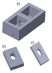
Figure 1. 3D design of (a) a dual-chamber MFC reactor, (b) anode cover, (c) Cathode cover.
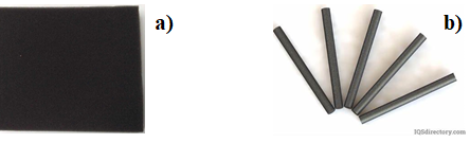
Figure 2. a) Carbon foam electrode, b) Graphite rod electrode.
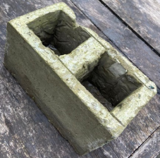
Figure 3. Dual-chamber MFC molding reactor.
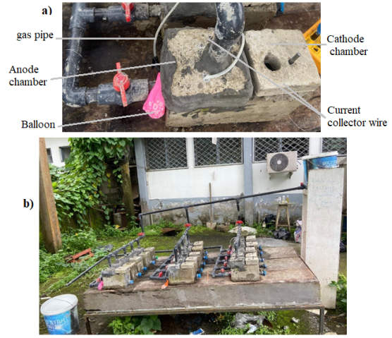
Figure 4. Concrete base dual-chamber MFC: (a) One MFC reactor and (b) The entered system.
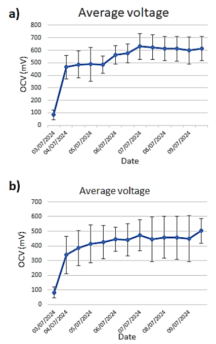
Figure 5. Average OCV curves (a) using graphite rod cathode electrodes, (b) using carbon foam cathode electrodes.
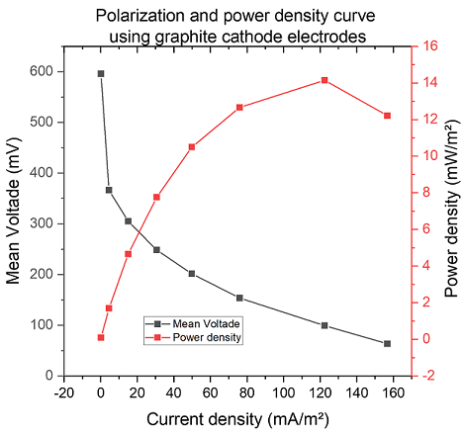
Figure 6. Polarization and power density curve for the MFC using graphite rod as cathode electrode.
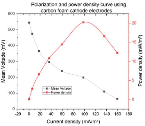
Figure 7. Polarization and power density curve for the MFC using carbon foam as cathode electrode.
Information