Abstract
The supercavitating underwater vehicle is affected by the hydrodynamic forces acting on the cavitator, body and fins, and thrust force of the engine, and these external forces affect the natural vibration of the supercavitating underwater vehicle. Accurate analysis of natural frequencies and natural modes has a great importance in the structural design of supercavitating underwater vehicles. In this paper, a Euler-Bernoulli beam model with a non-uniform cross section was applied to analyze the natural vibration characteristics of the supercavitating underwater vehicle more accurately. Also, the force characteristics acting on the supercavitating underwater vehicle with different speeds, angles of attack, cavitation numbers, fin positions and mass variations were analyzed and the natural vibration characteristics were analyzed by applying the Riccati transfer matrix method. The main influence of the natural vibration characteristics on the analysis of the natural vibration characteristics of supercavitating underwater vehicles by applying the Euler-Bernoulli beam theory through the calculation results is the distribution of the axial force formed by the total external force and the mass change characteristic. Also, the natural vibration characteristics of the system are sensitive to changes in cavitation number, angle of attack, vehicle velocity, fin position, and mass distribution, so that the change in the characteristic of the system can be accurately analyzed to ensure the reliability of the structural design.
Keywords
Supercavitation, Cavitation Number, Natural Vibration, Euler-Bernoulli Beam, RTMM
1. Introduction
With the intensified research on supercavitating underwater vehicle, more accurate, faster and easy analysis of structure vibration of the vehicle is important in putting the design of the vehicle structure on a scientific basis and reducing the cost.
In general, the characteristic of the longitudinal force acting on the vehicle, including missile, changes its natural vibration characteristics
| [1] | Gangli Chen, Xiaoting Rui, et al. “Study on the Natural Vibration Characteristics of Flexible Missile With Thrust by Using Riccati Transfer Matrix Method”. Journal of Applied Mechanics 2016; 83: 031006. |
[1]
. In particular, during the initial starting and accelerating motion, various control forces are generated, which complicate the external force acting on the vibration characteristics of the underwater vehicle.
Changes in the structural response due to external force and internal structural changes in the supercavitating underwater vehicle change the natural vibration characteristics of the system.
Especially, electrical components, including the control unit, are very sensitive to high frequency vibrations of 20-2000 Hz
| [2] | Yin YY, Zivanovic S, Li DX. “Displacement Modal Identification Method of Elastic System Under Operational Condition”. Nonlinear Dynamics 2012; 70(2); 1407–1420. |
[2]
. Therefore, the characteristic of the natural vibrations in the design of the electrical element substructure should be analyzed more accurately.
Theoretical studies on various structural vibrations of supercavitating underwater vehicles have already been studied by many engineers.
YANG Chuan-wu
et al.
| [3] | YANG Chuan wu, WANG An wen. “Influence of dynamic axial loads on the vibration characteristics of supercavitation underwater vehicle”. J. Huazhong Univ. of Sci. & Tech 2008; 36(12): 71-74. |
[3]
analyzed the longitudinal vibration modeling method of supercavitating underwater vehicle and the effect of time-dependent dynamic loading on the natural vibration characteristics in their study on the effect of axial dynamic loading on the vibration characteristics of supercavitating underwater vehicle.
Alyanak E
et al.
| [4] | Alyanak E, Venkayya V, Grandhi R, et al. “Structural response and optimization of a supercavitating torpedo”. Finite Elements in Analysis and Design 2005; 41(6): 563-582. |
[4]
applied finite element analysis method to analyze the structural response of supercavitating underwater vehicle and proposed an optimization method for structural design problems with reasonable natural frequencies to avoid resonance.
Kunlkarni S S
et al.
| [5] | Kulkarni S S, Pratap R. “Studies on the dynamics of a supercavitating projectile”. Applied Mathematical Modeling 2000; 24: 113-129. |
[5]
presented a mathematical model for the analysis of the dynamic characteristics of a super-cavitating underwater projectile in their study of the structural vibration of a super-cavitating projectile and discussed the problems of numerical stability.
In the analysis of the previous literature on structural vibration analysis of supercavitating underwater vehicle, structural vibration was considered by applying finite element method and shell theory, but the natural frequency variation characteristics of structural vibration with varying external force characteristics and mode change characteristics were less discussed.
In the study of structural vibrations of missiles, the Euler-Bernoulli beam theory and the Timoshenko beam theory are used as the basic theories important in the formulation of governing equations of structural vibrations
| [1] | Gangli Chen, Xiaoting Rui, et al. “Study on the Natural Vibration Characteristics of Flexible Missile With Thrust by Using Riccati Transfer Matrix Method”. Journal of Applied Mechanics 2016; 83: 031006. |
[1]
.
Vernon
et al.
| [6] | Vernon LA, Jr Robert, JG, Leessie D H. “A Method of Determining Modal Data of a Nonuniform Beam With Effects of Shear Deformation and Rotary Inertia”. NASA Langley Research Center 1965; NASA TN D-2930. |
[6]
studied the structural vibration of a missile considering the influence of rotary inertia and shear deformation. Numerical results showed that the effects of rotary inertia and shear deformation have no significant effect on the low-order natural vibrations.
Many methods used in vibration studies of discrete beam structures include finite element method, separation of variables and multi-system transfer matrix method
| [1] | Gangli Chen, Xiaoting Rui, et al. “Study on the Natural Vibration Characteristics of Flexible Missile With Thrust by Using Riccati Transfer Matrix Method”. Journal of Applied Mechanics 2016; 83: 031006. |
| [7] | Rui XT, Yun LF, Lu YQ, He B, Wang G P. “Transfer Matrix Method for Multibody System and Its Application”, Science Press 2008. |
| [8] | Pestel EC, Leckie FA, “Matrix Method in Elastomechanics”, McGraw-Hill 1963. |
| [14] | Edward Alyanak et al, “Structural response and optimization of a supercavitating torpedo”, ELSEVIER, Finite elements in Analysis and Design 2005; 41: 563-582. |
[1, 7, 8, 14]
.
The interest in the analysis of the natural vibration characteristics of beam structures, such as supercavitating underwater vehicles, is the application of the multibody transfer matrix method.
Gangli Chen
et al.
| [1] | Gangli Chen, Xiaoting Rui, et al. “Study on the Natural Vibration Characteristics of Flexible Missile With Thrust by Using Riccati Transfer Matrix Method”. Journal of Applied Mechanics 2016; 83: 031006. |
[1]
applied the transfer matrix method model in the study of missile structural vibrations under constant axial loading. Analyzing the computational results, the Riccati transfer matrix method is superior in terms of computational cost reduction, solution stability and accuracy of the computational results in the application of finite element method, separation of variables and transfer matrix method
| [9] | Yu XD, Duan, DG, Zhao W. “Riccati Method for Vibration Characteristics Analysis of the Missile”, J. Projectiles, Rockets, Missile Guid. 1994; 2: 47-55. |
[9]
.
In this paper, the natural vibration characteristics of supercavitating underwater vehicles are analyzed by applying the supercavitation theory, the Euler-Bernoulli beam theory and the Riccati transfer matrix method.
The paper is organized as following 6 sections. In Section 2, based on the supercavitation theory, a mathematical model is developed to analyze the hydrodynamic force characteristics acting on the supercavitating underwater vehicle. The Vasin model for cavitation profile determination, hydrodynamic resistance determination of disk cavitation generator, fin resistance and gliding force characteristics with immersion depth were analyzed. In Section 3, mathematical modeling of structural vibrations of supercavitating underwater vehicles under static equilibrium conditions and different motion conditions is carried out to analyze the factors that have a major influence on structural vibrations. In Section 4, the natural vibration characteristics analysis of supercavitating underwater vehicle is analyzed by applying the Riccati transfer matrix method, and an example of its calculation is presented in Section 5. In Section 5, the analysis of the natural vibration characteristics of the drag with velocity variations, angle of attack variations, position variations of the fin and mass variations under different constant-speed conditions is carried out, and conclusions are drawn in Section 6.
2. Hydrodynamic Force Analysis on a Supercavitating Underwater Vehicle
For a supercavitating underwater vehicle to travel at high speed, the vehicle is subjected to thrust and various hydrodynamic forces, thereby changing the natural vibration characteristics of the vehicle.
Many studies have been carried out on the hydrodynamic forces acting on the supercavitating underwater vehicle and the external force acting on the natural vibration characteristics.
The external forces acting on the supercavitating underwater vehicle are the resistance acting on the cavitator, the planning force determined by the wetting characteristics of the drag at the interface of the cavity, the control force acting on the guide vane, and the thrust force and gravity.
These hydrodynamic forces are determined by the cavitation characteristics.
In representing cavitation, a dimensionless number called cavitation number is used mainly, whose physical expression is as follows.
| [10] | AD Vasin, “The Principle of Independence of the Cavity Sections Expansion(Logvinovich’s Principle) as the Basis for Investigation on Cavitation Flows”. RTO AVT Lecture Series on Supercavitating Flows. North Atlantic Treaty Organization 2001; 8: 1-28. |
[10]
.
Where, is static pressure at a depth
- saturation pressure of water
– water density
V – vehicle velocity
The resistance acting on the cavitator depends on cavitation number, which is expressed by the following formula.
| [11] | Yu N Savchenko, “Supercavitating Object Propulsion. RTO AVT Lecture Series on Supercavitating Flows”. North Atlantic Treaty Organization 2001; 17: 1-30. |
[11]
.
For a disk cavitator with an angle of attack for horizontal flow, the hydrodynamic force acting on it is expressed as
where is the drag coefficient, which depends on the cavitation number and is determined by following empirical value.
is the area of the cavitator, which is calculated with respect to the diameter .
If the cavitator has an angle of attack
, the resistance
and lift
of the cavitator are
| [12] | Yu N Savchenko, “Control of Superavitation Flow and Stability of Supercavitating Motion of Bodies”. RTO AVT Lecture Series on Supercavitating Flows. North Atlantic Treaty Organization 2001; 14: 1-30. |
| [13] | Guoliang Zhao et al, “Control of Supercavitating Vehicles in the Vertical Plane Using Sliding Mode”, Proceedings of the 2008 IEEE 2009: 1800-1805. |
[12, 13]
:
By using Vasin’s cavitation model, the cavity profile formed by such a disk cavitator is expressed as
| [11] | Yu N Savchenko, “Supercavitating Object Propulsion. RTO AVT Lecture Series on Supercavitating Flows”. North Atlantic Treaty Organization 2001; 17: 1-30. |
| [12] | Yu N Savchenko, “Control of Superavitation Flow and Stability of Supercavitating Motion of Bodies”. RTO AVT Lecture Series on Supercavitating Flows. North Atlantic Treaty Organization 2001; 14: 1-30. |
[11, 12]
:
(9)
where is the maximum diameter of the cavity, is the cavity length, and is the cavity radius with respect to the position.
Then the rise height
due to the action of gravity is determined by experimental formula as follows
| [11] | Yu N Savchenko, “Supercavitating Object Propulsion. RTO AVT Lecture Series on Supercavitating Flows”. North Atlantic Treaty Organization 2001; 17: 1-30. |
[11]
.
where is the dimensionless length, is the Froude number and is
Also, the distortion height
due to the angle of attack is determined by experimental formula as follows
| [11] | Yu N Savchenko, “Supercavitating Object Propulsion. RTO AVT Lecture Series on Supercavitating Flows”. North Atlantic Treaty Organization 2001; 17: 1-30. |
[11]
.
(13)
where is the body attitude angle and is the attack angle of a cavitator.
When an underwater vehicle is placed in this determined cavitation profile, the force acting on the stabilizer fin under different submergence conditions is expressed as
| [13] | Guoliang Zhao et al, “Control of Supercavitating Vehicles in the Vertical Plane Using Sliding Mode”, Proceedings of the 2008 IEEE 2009: 1800-1805. |
[13]
:
where, - fin drag coefficient, which is determined as
- immerged depth of fin
- fin thickness
- cavitation number
When the underwater vehicle is in a gliding state, the planning force acting on the underwater vehicle is expressed as follows
| [15] | Perte J, KCameron et al. “An Experiment for the Study of Free-Flying Spercavitating Projectiles”, Journal of Fluids Engineering 2011; 133: 021303. |
[15]
:
(16)
Where
- dynamic viscosity of the water
-wetted length
- wetting angle
(17)
3. Mathematical Modeling
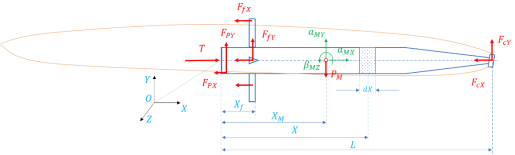
When the supercavitating underwater vehicle is moving underwater, the vehicle is translating and rotating around its center of mass under the influence of the external forces.
Then, from Newton's second law, the translational and rotational accelerations are determined as follows (
Figure 1).
(18)
(19)
(20)
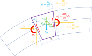
Let us consider the free vibration characteristics of a beam under the action of external forces. The beam model uses the Euler-Bernoulli beam model. First, let us consider the internal force characteristics acting on an infinitesimal element caused by external forces (
Figure 2).
Figure 2. Forces acting on an infinitesimal element with uniform cross-section.
The internal force in the horizontal direction caused by the effect of the external forces acting in the horizontal direction is
Hence, the horizontal compressive force acting on the ith component is expressed as
(22)
The internal shear force in the vertical direction due to the influence of the external forces is
(23)
Hence, the vertical force acting on the ith element is expressed as
(24)
The shear force generated in the vertical direction are
Hence, the internal bending moment acting on the ith element is expressed as
(26)
To investigate the free vibrations when a beam is subjected to external forces., the displacements are assumed to be the sum of the static and vibrational displacements.
.
Where - directional static displacement
- directional static displacement
- directional vibrational displacement
- directional vibrational displacement
When applying the Euler-Bernoulli beam theory, the force balance condition gives the following relation:
(30)
The following relationship holds for the material mechanics:
From Eq. (
31), the x-direction force balance of the dx infinitesimal element is given by
(33)
Dividing the vibration displacement and the static displacement, the Eq.(
33) is expressed as following Eq.(
34) and Eq.(
35).
The moment balance condition for the right end point of the infinitesimal element is established as
(36)
By ordering Eq. (
36), taking partial derivatives with respect to
and neglecting inertia term
, the following relation holds.
(37)
Taking into account Eq. (
30) in the above equation, the following relation is obtained:
(38)
Separating the static and vibrational displacements, the following equations are obtained:
(39)
(40)
As can be seen from Eq. (
34) ~Eq. (
39), the static force action causes the longitudinal and bending static deformation of the beam, and the contribution to the vibration is the component of the
-direction force.
This is consistent with the free vibration results of beams subjected to axial compression loading when considered in the Euler-Bernoulli beam theory
| [1] | Gangli Chen, Xiaoting Rui, et al. “Study on the Natural Vibration Characteristics of Flexible Missile With Thrust by Using Riccati Transfer Matrix Method”. Journal of Applied Mechanics 2016; 83: 031006. |
[1]
.
4. Analysis of the Natural Vibration Characteristics by RTMM
RTMM is a transfer matrix method that introduces the Riccati transformation.
RTMM is a method that makes the analysis of high-order natural frequency characteristics more accurate by improving the numerical instability of the solution significantly by only initializing the boundary value problem compared to the transfer matrix method
| [1] | Gangli Chen, Xiaoting Rui, et al. “Study on the Natural Vibration Characteristics of Flexible Missile With Thrust by Using Riccati Transfer Matrix Method”. Journal of Applied Mechanics 2016; 83: 031006. |
[1]
.
When performing free vibration, the vibration displacements , , angular displacement , internal bending moment , and internal force ,, respectively can be written in the following form:
Where is the natural angular velocity of the vehicle and denotes the imaginary unit.
Also, and are the corresponding displacement, angular displacement, internal bending moment and mode coordinates of internal force, respectively.
The general solution of the equation (
34) and (
39) is expressed as
(48)
(49)
where are constants that satisfy both boundary conditions and initial conditions of transverse bending vibrations of the beam, are constants that satisfy the boundary and initial conditions of longitudinal vibrations, and .
is expressed from the characteristic equation with four roots, which are , , as follows:
From the transverse bending mode Y and Eq. (
39), the angular displacement
, the internal bending moment
, and the Y-direction internal shear force
are expressed as
From the horizontal vibration mode X, the internal compressive force is
To apply the transfer matrix method, the state quantities of the two ends of a beam with uniform cross-section can be defined as follows:
(56)
Eq.(
48)-Eq.(
55) can be written in matrix form as follows.
(58)
Where ,,,,,
The coefficient matrix in the 1st element is expressed as
Substituting Eq.(
60) into Eq.(
57)
where is the transfer matrix and the transfer matrix in the ith beam region with uniform cross-section is expressed as follows:
According to the principle of transfer matrix method, the transfer matrix of the whole domain of the vehicle is expressed as
(63)
The free boundary conditions of the underwater vehicle are
(64)
(65)
From these boundary conditions, the characteristic equation is obtained as follows:
(66)
From the solution of the characteristic equation by TMM, the calculation of the natural angular frequency is easy to program and has a high computational speed
| [1] | Gangli Chen, Xiaoting Rui, et al. “Study on the Natural Vibration Characteristics of Flexible Missile With Thrust by Using Riccati Transfer Matrix Method”. Journal of Applied Mechanics 2016; 83: 031006. |
[1]
. However, numerical instability can be found in high-order eigenfrequency calculations or in the calculation of eigen-frequency of long-chain systems. The main reason is that the hyperbolic functions contained in the transfer matrix have no restriction on (0,+∞) with monotonic growth.
Also, in the calculation of the transfer matrix of the whole system, the round-off errors accumulate and rapidly increase with increasing frequency, leading to numerical instability. To overcome this, we must introduce the Riccati transformation. The state vector Z is divided into two parts as follows:
(68)
(69)
The transfer matrix of the ith beam segment is divided by
(70)
The relation between the left state vector and the right state vector of the ith beam segment interval is expressed by the transfer matrix as follows:
(71)
Setting the Riccati transform
between the substate vectors
and
, we can write
| [1] | Gangli Chen, Xiaoting Rui, et al. “Study on the Natural Vibration Characteristics of Flexible Missile With Thrust by Using Riccati Transfer Matrix Method”. Journal of Applied Mechanics 2016; 83: 031006. |
[1]
:
(72)
where is the Riccati transformation matrix at the junction i, i-1.
Substituting Eq.(
72) into Eq.(
71).
(73)
Finally, from Eqs. (
72) and (
73), the Riccati transformation matrix is expressed by the following recursion relation:
(74)
From the boundary conditions at both ends of the free end,
(76)
(78)
Eq. (
78) is a linear homogeneous differential equation and to have a solution for any nonzero solution, the value of the determinant of the characteristic equation
must be zero.
Finally, becomes a characteristic equation.
The RTMM has the advantage of overcoming numerical instability of the transfer matrix method and suppressing the propagation of the round-off error.
To make the numerical calculation easier, we must overcome the asymmetric poles, so we can introduce the following sign function:
(80)
Hence, the transfer matrix relationship of each beam element can be used to calculate the mode.
(81)
From the above expression, we can find the constant factor using the boundary condition and apply the transfer matrix to determine the state vector in the whole section.
5. Computational Examples and Analysis
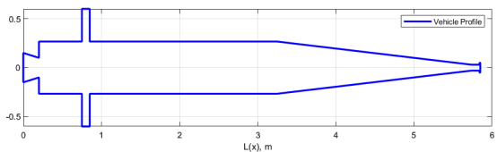
To analyze the effect of forces on the natural vibration characteristics of the supercavitating underwater vehicle, the following vehicle model were analyzed.
Figure 3. Model of supercavitating underwater vehicle.
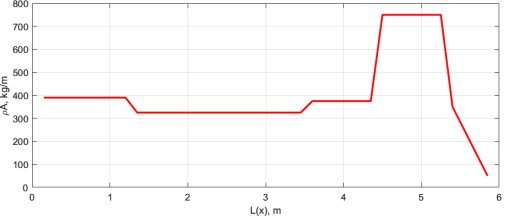
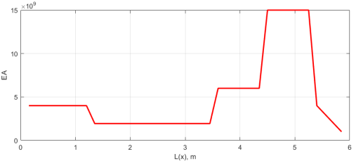
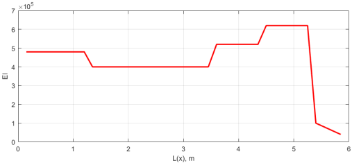
The mass distribution, longitudinal stiffness distribution and transverse stiffness distribution of this term are shown in
Figures 4, 5 and 6.
Figure 4. Mass distribution of the vehicle along its length.
Figure 5. Longitudinal stiffness of the vehicle along its length.
Figure 6. Transverse stiffness of the vehicle along its length.
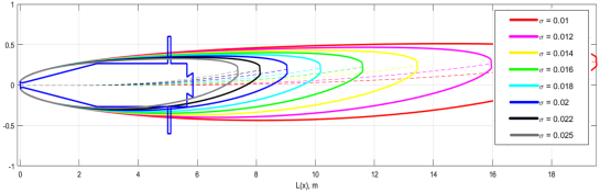
From Eq.(
7)~Eq.(
13), the cavitation profiles of the vehicle versus cavitation number variations when the attack angle of the cavitator is 10 degrees are shown in
Figure 7.
Figure 7. Characteristics of the cavitation profile variation of the vehicle versus cavitation number variation when the attack angle of the cavitator is 10 degrees.
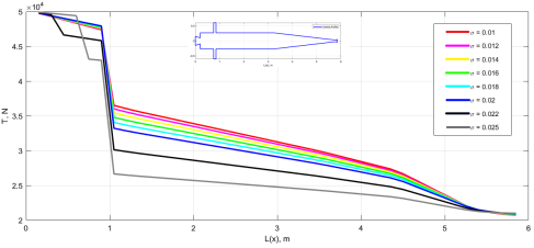
Then the longitudinal force characteristic acting on the vehicle is as follows.
Figure 8. Longitudinal Force Characteristics on a Supercavitating Underwater Vehicle.
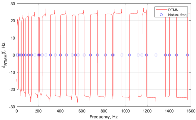
For = 0.025, from the characteristic equation of the Riccati transfer matrix method is
Figure 9. Solution of the characteristic equation when the cavitation number is 0.025.
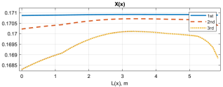
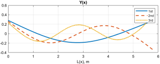
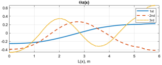
For , the vibration modes with respect to the axial force are
Figure 10. The x-direction mode considering axial force for cavitation number 0.025.
Figure 11. Y-Axial Mode with Cavitation Number 0.025.
Figure 12. Rotating angle mode with cavitation number 0.025.
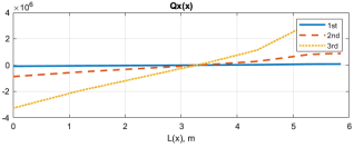
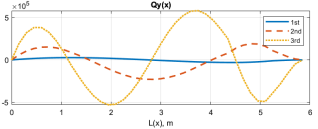
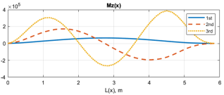
For, the internal force diagram of the natural vibration considering the axial force is
Figure 13. The x-axis compressive force with cavitation number 0.025.
Figure 14. Y-axis shear force with cavitation number 0.025.
Figure 15. The z-axis moment with cavitation number 0.025.
When the vehicle velocity and the attack angle, the natural frequencies with the change of cavitation numbers are
Table 1. Results of natural frequency calculations with varying cavitation number.
Cavitation number | Mode number(Hz) |
1 | 2 | 3 | 4 | 5 | 6 |
| 3.233 4 | 10.527 9 | 20.669 5 | 33.664 8 | 48.55 4 | 64.077 3 |
| 3.236 7 | 10.529 0 | 20.670 4 | 33.665 8 | 48.556 2 | 64.078 1 |
| 3.239 3 | 10.530 4 | 20.671 6 | 33.667 0 | 48.557 1 | 64.079 1 |
| 3.242 3 | 10.532 0 | 20.673 0 | 33.668 3 | 48.558 3 | 64.080 3 |
| 3.245 7 | 10.533 8 | 20.674 5 | 33.669 9 | 48.559 6 | 64.081 7 |
| 3.250 0 | 10.536 1 | 20.676 5 | 33.671 9 | 48.561 3 | 64.083 5 |
| 3.273 7 | 10.550 3 | 20.687 9 | 33.682 2 | 48.570 1 | 64.092 3 |
| 3.303 5 | 10.566 6 | 20.700 8 | 33.694 6 | 48.581 7 | 64.104 8 |
When the vehicle has the cavitation number and the attack angle of cavitator is 1, the natural frequencies with the velocity variation are
Table 2. Results of the calculation of natural frequencies with velocity variations.
| Mode number(Hz) |
1 | 2 | 3 | 4 | 5 | 6 |
| 3.348 6 | 10.627 4 | 20.778 0 | 33.800 4 | 48.784 8 | 64.311 6 |
| 3.332 9 | 10.611 7 | 20.759 8 | 33.776 7 | 48.742 0 | 64.267 2 |
| 3.299 9 | 10.581 2 | 20.726 0 | 33.734 1 | 48.667 9 | 64.191 2 |
| 3.249 9 | 10.536 0 | 20.676 5 | 33.671 9 | 48.561 3 | 64.083 5 |
| 3.187 5 | 10.479 3 | 20.613 5 | 33.591 7 | 48.423 0 | 63.946 2 |
| 3.107 4 | 10.407 9 | 20.534 3 | 33.490 2 | 48.249 3 | 63.777 9 |
| 3.006 2 | 10.319 8 | 20.436 7 | 33.364 8 | 48.037 3 | 63.578 2 |
| 2.879 7 | 10.212 7 | 20.318 5 | 33.212 2 | 47.783 2 | 63.347 0 |
When the vehicle has velocity and cavitation number, the natural frequency of the change in the angle of attack of the cavitator is
Table 3. Results of natural frequency calculations with angle of attack variation.
| Mode number(Hz) |
1 | 2 | 3 | 4 | 5 | 6 |
| 3.249 5 | 10.534 9 | 20.674 5 | 33.668 7 | 48.554 6 | 64.076 7 |
| 3.248 4 | 10.534 5 | 20.674 5 | 33.669 0 | 48.555 9 | 64.078 0 |
| 3.250 0 | 10.536 1 | 20.676 5 | 33.671 9 | 48.561 3 | 64.083 5 |
| 3.255 8 | 10.540 7 | 20.681 5 | 33.678 1 | 48.571 5 | 64.093 7 |
| 3.264 3 | 10.547 4 | 20.688 6 | 33.686 8 | 48.585 4 | 64.107 8 |
| 3.274 6 | 10.555 7 | 20.697 4 | 33.697 5 | 48.602 6 | 64.125 2 |
| 3.286 6 | 10.565 2 | 20.707 5 | 33.709 9 | 48.622 4 | 64.145 2 |
When the vehicle has velocity , cavitation number, and attack angle of cavitator, the natural frequency depending on the position of the stabilizer fin is
Table 4. Calculation results of natural frequencies according to the position of the fin.
| Mode number (Hz) |
1 | 2 | 3 | 4 | 5 | 6 |
| 3.2500 | 10.5361 | 20.6765 | 33.6719 | 48.5613 | 64.0835 |
| 3.2729 | 10.5507 | 20.6844 | 33.6753 | 48.5623 | 64.0845 |
| 3.285 6 | 10.5601 | 20.6913 | 33.6804 | 48.5653 | 64.0865 |
| 3.2989 | 10.5704 | 20.6996 | 33.6876 | 48.5707 | 64.0912 |
| 3.3253 | 10.5916 | 20.7051 | 33.7051 | 48.5853 | 64.1060 |
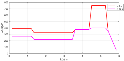
The natural frequencies of the supercavitating underwater vehicle with the mass change of the system at the beginning and at the end of the launch are as follows.
Figure 16. Mass distribution along the length at the beginning stage t=0s and at the steady state t=10s.
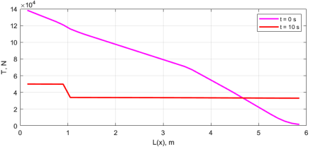
Then, the axial compressive force distribution is calculated as follows:
Figure 17. Axial compression force distribution.
Hence, the natural frequency characteristic is analyzed as follows:
Table 5. Results of the calculation of natural frequencies in the starting stage and the steady-state stage.
| Mode number(Hz) |
| | | | | 1 | 2 | 3 | 4 | 5 | 6 |
20 | 0.02 | 5 | 120 000 | 10 | 2.4221 | 10.075 5 | 20.343 7 | 33.408 0 | 48.453 2 | 63.985 8 |
150 | 0.01 | 5 | 50 000 | 5 | 3.693 5 | 11.888 0 | 24.246 2 | 38.804 2 | 55.630 2 | 74.299 8 |
The results from
Tables 1-5 show that variations of various parameters change the axial force distribution of the Supercavitating Torpedo and this axial force distribution is serious for the natural vibration characteristic of the Supercavitating underwater vehicles.
6. Conclusions
In this paper, we analyzed the natural vibration characteristics of the underwater supercavitating vehicle with different parameters variations. The Euler-Bernoulli beam theory and the Riccati transfer matrix method were used to analyze the natural vibration characteristics. Results shows that axial force distribution and mass variation significantly affect the natural vibration characteristics, and this consideration is important for structural design.
Abbreviations
TMM | Transfer Matrix Method |
RTMM | Riccati Transfer Matrix Method |
Acknowledgments
This paper received no specific grant from the public, commercial, or not-for-profit funding agencies.
Author Contributions
Se Ryung Jo: Conceptualization, Methodology, Writing – review & editing
Chol Hun Kim: Conceptualization, Methodology, Validation, Visualization, Writing – original draft
Kwang Il Ri: Conceptualization, Data curation, Visualization, Writing – review & editing
Conflicts of Interest
The authors declare no conflicts of interest.
References
| [1] |
Gangli Chen, Xiaoting Rui, et al. “Study on the Natural Vibration Characteristics of Flexible Missile With Thrust by Using Riccati Transfer Matrix Method”. Journal of Applied Mechanics 2016; 83: 031006.
|
| [2] |
Yin YY, Zivanovic S, Li DX. “Displacement Modal Identification Method of Elastic System Under Operational Condition”. Nonlinear Dynamics 2012; 70(2); 1407–1420.
|
| [3] |
YANG Chuan wu, WANG An wen. “Influence of dynamic axial loads on the vibration characteristics of supercavitation underwater vehicle”. J. Huazhong Univ. of Sci. & Tech 2008; 36(12): 71-74.
|
| [4] |
Alyanak E, Venkayya V, Grandhi R, et al. “Structural response and optimization of a supercavitating torpedo”. Finite Elements in Analysis and Design 2005; 41(6): 563-582.
|
| [5] |
Kulkarni S S, Pratap R. “Studies on the dynamics of a supercavitating projectile”. Applied Mathematical Modeling 2000; 24: 113-129.
|
| [6] |
Vernon LA, Jr Robert, JG, Leessie D H. “A Method of Determining Modal Data of a Nonuniform Beam With Effects of Shear Deformation and Rotary Inertia”. NASA Langley Research Center 1965; NASA TN D-2930.
|
| [7] |
Rui XT, Yun LF, Lu YQ, He B, Wang G P. “Transfer Matrix Method for Multibody System and Its Application”, Science Press 2008.
|
| [8] |
Pestel EC, Leckie FA, “Matrix Method in Elastomechanics”, McGraw-Hill 1963.
|
| [9] |
Yu XD, Duan, DG, Zhao W. “Riccati Method for Vibration Characteristics Analysis of the Missile”, J. Projectiles, Rockets, Missile Guid. 1994; 2: 47-55.
|
| [10] |
AD Vasin, “The Principle of Independence of the Cavity Sections Expansion(Logvinovich’s Principle) as the Basis for Investigation on Cavitation Flows”. RTO AVT Lecture Series on Supercavitating Flows. North Atlantic Treaty Organization 2001; 8: 1-28.
|
| [11] |
Yu N Savchenko, “Supercavitating Object Propulsion. RTO AVT Lecture Series on Supercavitating Flows”. North Atlantic Treaty Organization 2001; 17: 1-30.
|
| [12] |
Yu N Savchenko, “Control of Superavitation Flow and Stability of Supercavitating Motion of Bodies”. RTO AVT Lecture Series on Supercavitating Flows. North Atlantic Treaty Organization 2001; 14: 1-30.
|
| [13] |
Guoliang Zhao et al, “Control of Supercavitating Vehicles in the Vertical Plane Using Sliding Mode”, Proceedings of the 2008 IEEE 2009: 1800-1805.
|
| [14] |
Edward Alyanak et al, “Structural response and optimization of a supercavitating torpedo”, ELSEVIER, Finite elements in Analysis and Design 2005; 41: 563-582.
|
| [15] |
Perte J, KCameron et al. “An Experiment for the Study of Free-Flying Spercavitating Projectiles”, Journal of Fluids Engineering 2011; 133: 021303.
|
| [16] |
Febg Liang, Zhen Li et al. “Coupled Bending–Bending–Axial–Torsional Vibrations of Rotating Blades”, ACTA MECHANICA SOLIDA SINICA 2019.
https://doi.org/10.1007/s10338-019-00075-w
|
Cite This Article
-
APA Style
Jo, S. R., Kim, C. H., Ri, K. I. (2026). Analysis of the Natural Vibration Characteristics of a Supercavitating Underwater Vehicle Considering Hydrodynamic Conditions. International Journal of Fluid Mechanics & Thermal Sciences, 12(1), 1-15. https://doi.org/10.11648/j.ijfmts.20261201.11
 Copy
|
Copy
|
 Download
ACS Style
Jo, S. R.; Kim, C. H.; Ri, K. I. Analysis of the Natural Vibration Characteristics of a Supercavitating Underwater Vehicle Considering Hydrodynamic Conditions. Int. J. Fluid Mech. Therm. Sci. 2026, 12(1), 1-15. doi: 10.11648/j.ijfmts.20261201.11
Copy
|
Download
AMA Style
Jo SR, Kim CH, Ri KI. Analysis of the Natural Vibration Characteristics of a Supercavitating Underwater Vehicle Considering Hydrodynamic Conditions. Int J Fluid Mech Therm Sci. 2026;12(1):1-15. doi: 10.11648/j.ijfmts.20261201.11
Copy
|
Download
-
@article{10.11648/j.ijfmts.20261201.11,
  author = {Se Ryung Jo and Chol Hun Kim and Kwang Il Ri},
  title = {Analysis of the Natural Vibration Characteristics of a Supercavitating Underwater Vehicle Considering Hydrodynamic Conditions},
  journal = {International Journal of Fluid Mechanics & Thermal Sciences},
  volume = {12},
  number = {1},
  pages = {1-15},
  doi = {10.11648/j.ijfmts.20261201.11},
  url = {https://doi.org/10.11648/j.ijfmts.20261201.11},
  eprint = {https://article.sciencepublishinggroup.com/pdf/10.11648.j.ijfmts.20261201.11},
  abstract = {The supercavitating underwater vehicle is affected by the hydrodynamic forces acting on the cavitator, body and fins, and thrust force of the engine, and these external forces affect the natural vibration of the supercavitating underwater vehicle. Accurate analysis of natural frequencies and natural modes has a great importance in the structural design of supercavitating underwater vehicles. In this paper, a Euler-Bernoulli beam model with a non-uniform cross section was applied to analyze the natural vibration characteristics of the supercavitating underwater vehicle more accurately. Also, the force characteristics acting on the supercavitating underwater vehicle with different speeds, angles of attack, cavitation numbers, fin positions and mass variations were analyzed and the natural vibration characteristics were analyzed by applying the Riccati transfer matrix method. The main influence of the natural vibration characteristics on the analysis of the natural vibration characteristics of supercavitating underwater vehicles by applying the Euler-Bernoulli beam theory through the calculation results is the distribution of the axial force formed by the total external force and the mass change characteristic. Also, the natural vibration characteristics of the system are sensitive to changes in cavitation number, angle of attack, vehicle velocity, fin position, and mass distribution, so that the change in the characteristic of the system can be accurately analyzed to ensure the reliability of the structural design.},
 year = {2026}
}
Copy
|
Download
-
TY  - JOUR
T1  - Analysis of the Natural Vibration Characteristics of a Supercavitating Underwater Vehicle Considering Hydrodynamic Conditions
AU  - Se Ryung Jo
AU  - Chol Hun Kim
AU  - Kwang Il Ri
Y1  - 2026/01/23
PY  - 2026
N1  - https://doi.org/10.11648/j.ijfmts.20261201.11
DO  - 10.11648/j.ijfmts.20261201.11
T2  - International Journal of Fluid Mechanics & Thermal Sciences
JF  - International Journal of Fluid Mechanics & Thermal Sciences
JO  - International Journal of Fluid Mechanics & Thermal Sciences
SP  - 1
EP  - 15
PB  - Science Publishing Group
SN  - 2469-8113
UR  - https://doi.org/10.11648/j.ijfmts.20261201.11
AB  - The supercavitating underwater vehicle is affected by the hydrodynamic forces acting on the cavitator, body and fins, and thrust force of the engine, and these external forces affect the natural vibration of the supercavitating underwater vehicle. Accurate analysis of natural frequencies and natural modes has a great importance in the structural design of supercavitating underwater vehicles. In this paper, a Euler-Bernoulli beam model with a non-uniform cross section was applied to analyze the natural vibration characteristics of the supercavitating underwater vehicle more accurately. Also, the force characteristics acting on the supercavitating underwater vehicle with different speeds, angles of attack, cavitation numbers, fin positions and mass variations were analyzed and the natural vibration characteristics were analyzed by applying the Riccati transfer matrix method. The main influence of the natural vibration characteristics on the analysis of the natural vibration characteristics of supercavitating underwater vehicles by applying the Euler-Bernoulli beam theory through the calculation results is the distribution of the axial force formed by the total external force and the mass change characteristic. Also, the natural vibration characteristics of the system are sensitive to changes in cavitation number, angle of attack, vehicle velocity, fin position, and mass distribution, so that the change in the characteristic of the system can be accurately analyzed to ensure the reliability of the structural design.
VL  - 12
IS  - 1
ER  -
Copy
|
Download