Research Article | | Peer-Reviewed

Compensation of the Reactive Power Consumed by the Transformer of the Mamou Electrical Substation

Received: 18 December 2025     Accepted: 31 December 2025     Published: 29 January 2026
Views:       Downloads:
Abstract

The continuous growth in electricity demand imposes increasing constraints on power transmission and distribution infrastructures, particularly in developing electrical networks. Among the key components of these systems, power transformers play a central role, while simultaneously contributing to reactive power consumption that affects voltage regulation and network efficiency. This study focuses on the compensation of reactive power absorbed by the power transformer of the Mamou electrical substation in Guinea. The investigated transformer is an oil-immersed unit rated at 15 MVA with a voltage level of 110 kV/30 kV. An analytical approach based on transformer operating characteristics is adopted to evaluate the reactive power requirements associated with magnetizing and leakage reactances. Using these formulations, the required rating of a shunt capacitor bank is determined in order to fully compensate the reactive energy consumed by the transformer. The results indicate that a capacitor bank rated at 2422.5 kVAr allows a significant reduction in apparent power and line current on the high-voltage side. Consequently, copper losses, Joule losses in the transmission line, and associated greenhouse gas emissions are reduced, leading to an annual energy saving of approximately 36,104 kWh. The findings highlight the technical and economic relevance of reactive power compensation for improving the operational performance of substations in emerging power systems.

Published in International Journal of Sustainable and Green Energy (Volume 15, Issue 1)
DOI 10.11648/j.ijsge.20261501.13
Page(s) 23-30
Creative Commons

This is an Open Access article, distributed under the terms of the Creative Commons Attribution 4.0 International License (http://creativecommons.org/licenses/by/4.0/), which permits unrestricted use, distribution and reproduction in any medium or format, provided the original work is properly cited.

Copyright

Copyright © The Author(s), 2026. Published by Science Publishing Group

Keywords

Transformer, Reactive Power Compensation, Mamou Substation

1. Introduction
All induction devices and machines that operate on alternating current systems convert electrical energy supplied by generators in the power system into mechanical work and heat. This energy is measured in KWh, and is called active energy. To perform this conversion, magnetic fields must be established in these machines. The most common of these machines are transformers, motors and discharge lamps with magnetic ballasts.
The proportion of reactive power to active power for full load operation is 65 to 75% for asynchronous motors, and 5 to 10% for transformers . Reactive energy consumption in a transformer increases reactive power losses, which causes voltage drops in distribution networks. .
In a transformer, reactive energy is absorbed by both parallel reactance (magnetizing flux) and series reactance (magnetic leakage flux). Power factor compensation can be achieved by a bank of capacitors . Complete compensation can be achieved by a bank of capacitors in parallel connected in LV. The power factor at the primary of the transformer is generally lower than that measured at the secondary due to the reactive power required by the transformer. If the metering is carried out at medium voltage, the additional reactive power consumed by the transformer will also be measured. In such cases, it is important to know the reactive power consumed by the transformer so that it can be subtracted from the reactive power demand of the load. Installing a capacitor bank can avoid changing the transformer during an extension.
An approach similar to that developed to reduce the subscribed power, increase the power factor of the load as described in previous work , makes it possible to increase the capacity of a transformer, i.e. to increase the active power available .
In this work, we study the compensation of the reactive energy absorbed by the transformer of the Mamou substation.
This work uses a simple and compact expression of the power of a bank of fixed capacitors for the compensation of the reactive power absorbed by the transformer itself, at different load conditions. It has been demonstrated that the installation of a bank of capacitors whose power corresponds to the nominal load, reduces the effective value of the current for all other loads without causing an overvoltage at no load.
2. Materials and Method
2.1. Materials
2.1.1. Presentation of the Study Area
The study is conducted in the prefecture of Mamou, which serves as the administrative capital of the Mamou region in the Republic of Guinea. The area is located between latitudes 9°54′ and 11°10′ North and longitudes 11°25′ and 12°26′ West, with an average altitude of approximately 700 m. Mamou occupies a strategic geographical position at the junction of major national transmission corridors, which makes it an important hub for electricity distribution in Middle Guinea . It is limited: to the North by the Prefectures of Dalaba and Tougue; to the South by the Republic of Sierra Leone; to the East by the Prefectures of Dabola and Faranah; to the West by the Prefecture of Kindia. Its climate is Foutanian type, characterized by the alternation of two (2) seasons of equal duration: a dry season from November to April and a rainy season from May to October . Its surface area is distributed between an urban commune which has 28 neighborhoods and 13 rural communities (CR), namely: Bouliwel, Dounet, Gongore, Kegneko, Konkoure, Niagara, Ourekaba, Poredaka, Saramoussaya, Soya, Teguereya, Timbo and Tolo. The population is mainly rural, 79% of the population of Mamou is located in rural areas. Its average density is 43 inhabitants/km² and its climate is tropical . According to the General Population and Housing Census, Mamou has 391,777 inhabitants in 2021 with an area of 2,350 km², or a density of 167 inhabitants per km². Mamou includes 28 neighborhoods including 5 districts which represent its peri-urban zone. These 5 districts are Madina Km 15 (North of the city), Sere (Northeast of the city); Koumi (East of the city); Teliko (South of the city) and Hore Mamou (Northwest of the city).
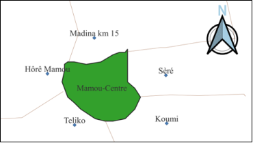
Figure 1. Map of the commune of Mamou.
2.1.2. Characteristics of the Mamou Substation Transformer
The Mamou electrical substation is a 110/30 kV distribution facility located approximately 6 km from the city center, in the Séré district along the Mamou–Dabola national road. The substation is supplied by the Linsan–Mamou transmission line, which forms part of the Garafiri power system.
The main transformer installed at the substation is a three-phase oil-immersed step-down transformer rated at 15 MVA, with a nominal voltage of 110 kV on the high-voltage (HV) side and 30 kV on the low-voltage (LV) side. It operates under ONAN/ONAF cooling modes and is equipped with an on-load tap changer that allows secondary voltage regulation. This transformer supplies electrical energy to the city of Mamou as well as neighboring localities through several outgoing feeders. The single-line configuration of the substation illustrates the role of the transformer as the central element in power distribution (Figure 2).
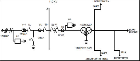
Figure 2. Single-line configuration of the Mamou substation.
2.1.3. Tools and Data Sources
The analysis is based on:
Nominal electrical parameters of the Mamou substation transformer,
Annual load statistics provided by the Electricity of Guinea (EDG) for the period 2018–2021,
Analytical expressions describing transformer reactive power consumption,
MATLAB software for numerical computation and simulation,
Microsoft Excel for data processing and graphical representation.
2.2. Method
The method used consists of determining the reactive energy consumed by the inductive components of the transformer from a mathematical expression, then defining the power of the bank of fixed capacitors to compensate for the reactive energy absorbed by the transformer itself . For the collection of data on the transformer load, we extracted the statistics of the load peaks of the artery of the Mamou substation through the annual statistics of the EDG for the years 2018, 2019, 2020 and 2021 . Then we determined the total consumption of the different feeders supplied by the transformer at the Mamou substation.
2.2.1. Reactive Power Absorbed by a Transformer
Power transformers consume reactive energy during operation . This is due to the reactive power requirements of two distinct branches of the transformer, namely: the shunt magnetization reactance and the series leakage reactance.
Considering that the reactive energy losses, the principal diagram of a transformer is defined in Figure 1. All the reactance is reported to the secondary of the transformer: the parallel reactance represents the magnetizing current circuit; the series reactance represents the magnetic losses.
The magnetizing current remains practically constant, at approximately 1.8% of the full load current whatever the load, in normal operation, that is to say with a constant primary voltage.
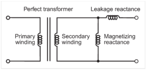
Figure 3. Schematic diagram of reactance per phase of a transformer.
(i). Reactive Power Absorbed in Leakage Reactance XL
The reactive power absorbed by a transformer cannot be neglected, and can be estimated at approximately 5% of the power of the transformer when it is operating at full load. The vector representation in Figure 2 illustrates this phenomenon.
The reactive component of the current in the load is: IrL= I sin φ hence:
QL = VI sin φ. (1)
The reactive component of the current in the source is IrE = I sin φ' hence:
QE = EI sin φ'. (2)
The difference between relation (1) and (2) determines the amount of reactive energy absorbed by the leakage reactance. From this representation, we deduce that the power linked to the magnetic leakage flux is given by:
P=I2XL(3)
From expression (3), we deduce the reactive leakage power dissipated for all the intensities of the load current of a transformer.
The vector representation in Figure 2 illustrates the reactive power dissipated by the series leakage inductance of a transformer.
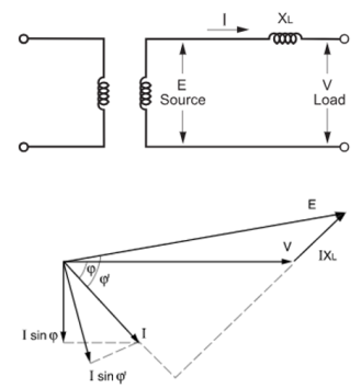
Figure 4. Reactive power dissipated by the series leakage inductance of a transformer.
To determine the total reactive losses of a transformer, it is necessary to add the losses due to constant magnetizing current to those previously calculated (reactive losses due to leakage flux).
(ii). Reactive Power Absorbed in the Shunt Magnetizing Reactance
The magnetizing shunt reactance is responsible for creating the magnetic flux in the transformer core. The current required to create this flow in the core is called excitation current and is relatively independent of the transformer load current. The excitation current is generally in the range of 0.25 to 2% of the transformer full load current. The actual value of excitation current can be obtained from the factory test report or can be measured in the field. To calculate the absorbed reactive power, one must first calculate the approximate shunt magnetizing impedance from the given excitation current. Excitation current is usually stated as a percentage of the transformer's full load current.
2.2.2. Power of the Fixed Capacitor Bank for Compensation of Reactive Energy Absorbed by a Transformer
The reactive losses of a transformer can be completely compensated by a bank of capacitors such that the power factor becomes very slightly ahead .
In each operating mode of the transformer, the capacitor bank must provide reactive power QC to compensate for the reactive energy of magnetization of the transformer Qµ and the reactive leakage energy QX :
 QC=Qμ+QX(4)
In no-load operation, the apparent Power of transformer is:
S0=3U0I0=3UrI0=PFe2+Qμ2(5)
Where: P Fe is the loss in the iron of the transformer.
The reactive power for the magnetization of the transformer is:
Qμ=3Ur2I02-PFe2=3UrIrI0Ir2-PFe2(6)
By introducing the value as a percentage of the no-load current: i0=I0Ir.100 expression (3) becomes:
Qμ=i0100Sr2-PFe2(7)
Where Sr is the rated power of the transformer.
In Short-Circuit Operation, the apparent power is:
SSC=3USCIr=PCur2+QXr2(8)
Where: Ir and Pcur are respectively the nominal current and the copper losses of the transformer at nominal load. Therefore, the reactive power lost in the leakage reactance of the transformer is:
QXr=3USCIr2-PCur2(9)
As, by definition, the impedance voltage is:
usc=USCUr100XSCIrUr.100(10)
Expression (6) becomes:
QXr=usc1003UrIr2-PCur2=usc100Sr2-PCur2(11)
For any other operating condition, when the transformer load is less than the nominal value, we have:
Qx=x2QXr=x2usc100Sr2-PCur2(12)
In general, for a load x, the power of the capacitor bank is:
QC=i0100Sr2-PFe2+x2usc100Sr2-PCur2(13)
When a quick and rough estimate of the power of the shunt capacitor banks is necessary, the following expression is used:
QC=i0100Sr+x2usc100Sr(14)
Where the losses in the transformer are neglected .
In the expression (14), appears the nominal apparent power of the transformer Sr, value as a percentage of impedance voltage u sc, load x of the transformer and the value as a percentage of the no-load current, i0. When a transformer operates with its secondary open-circuited (no-load condition) and rated voltage applied to the primary, it draws a small no-load current i0. This current serves to:
Establish the magnetic flux in the transformer core (magnetizing component).
Supply core losses (hysteresis and eddy current losses).
The no-load current as a percentage of rated current decreases as the rated power of the transformer increases.
Mathematically, a correlation often used in power engineering is :
i0=0.0421.logSr2-0.4384.logSr+1.6064(15)
Where Sr is the nominal apparent power of the transformer in MVA and i0 is the percentage value of the no-load current. Expression (15) conforms to the scaling laws of transformers.
Sr1Sr0-0.25
The active and reactive powers that the transformer absorbs on the high-voltage side are given by expressions (16) and (17).
 P110KV=PL+PFe+PCu(16)
Q110KV=QL+Qx+Qμ=QL+QC(17)
Therefore, the apparent power and phase current on the 110 kV side are:
S=P110kv2+Q110kv2(18)
 I110kv=S3U(19)
3. Results and Discussions
After compensation for the reactive power consumed by the transformer, by a capacitor banks of 2422.5. KVAr, the reactive power taken from the high voltage side (110kV) is equal to the reactive power of the load (Q 110kV =Q L), so that the apparent power and the current on the high voltage side are S= 11363.46kVA and I=60.76A. By full compensation in this operating condition, the input current is reduced by 5.5% and, therefore, the losses in the Linsan-Mamou cable under a voltage of 110 kV are reduced by 10.76%.
Table 1. Impact of compensation for reactive energy consumed by the transformer.

Sizes

Without compensation

With Compensation

Rated voltages [kV]

110/30

110/30

Active power P HV [kW]

11186.07

11186.07

Reactive power QHV [kVAr]

2000

4422.5

Apparent power SHV [kVA]

11363.46

12028.58

The current I HV [A]

60.76

64.32

Active loss in the Linsan-Mamou line [KW]

72354, 46

81072,76

3.1. Evolution of Transformer Consumption Depending on the Load Rate
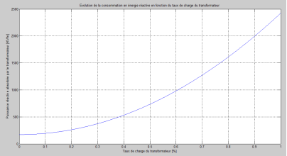
Figure 5. Evolution of transformer consumption as a function of load rate.
3.2. Evolution of the Reactive Energy Consumed at No Load Depending on the Power of the Transformer
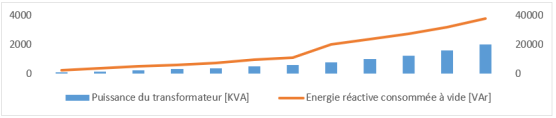
Figure 6. Evolution of reactive energy consumed at no load as a function of transformer power.
3.3. Evolution of the Reactive Energy Consumed at Full Load Depending on the Power of the Transformer
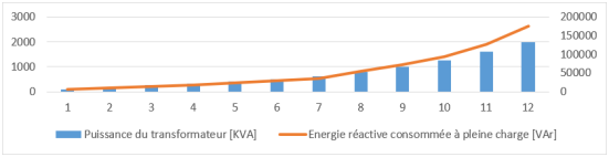
Figure 7. Evolution of reactive energy consumed at full load as a function of transformer power.
4. Conclusion
The research carried out is part of the compensation by a fixed capacitor bank, the reactive energy consumed by the transformer of the Mamou substation.
This study made it possible to determine the reactive power consumption elements (leakage reactance and magnetization reactance) of the transformer at the Mamou substation; and to determine the size of the capacitor bank required to compensate for the reactive power consumed by the transformer.
A mathematical expression was adopted and the simulation in MATLAB gave the following results (Figure 5). Before compensation, on the High Voltage side, we have an active power of 11186.07KW; a reactive power of 4422.5 KVAr; an apparent power of 12028.58KVA and a current of 64.32A. After compensation, we get a reduction in apparent power and current on the high voltage side (11363.46KVA, 60.76A). This reduction makes it possible to reduce Joule effect losses, losses in the copper of the transformer, an annual electrical energy saving of 36,104KWh and therefore a reduction in CO2 and SO2 emissions due to this energy saving.
Abbreviations

HV

High Voltage

EDG

Electricity of Guinea

ONAN

Oil Natural Circulation with Air Naturally Circulated for Cooling,

ONAF

Oil Natural Air Forced Cooling

Conflicts of Interest
The authors declare no conflicts of interest.
References
[1] Kosobudzki, G. ; Dusza, D. ; Ciurys, M. P. ; Leicht, A. Reactive Power Compensation for Single-Phase AC Motors Using Integral Power Theory. Energies 2025, 18, 2641.
[2] Jean Ouere TOUPOUVOGUI, Ansoumane SAKOUVOGUI, Mohamed Ansoumane CAMARA and Mamby KEITA, “Optimization of the Reactive Energy Compensation of the Guinea Brewerie Company Plant (SOBRAGUI)” International Journal of Progressive Sciences and Technologies (IJPSAT) Vol. 32 No. 2 May 2022, p. 159-167.
[3] Jean Ouere TOUPOUVOGUI, Mohamed Ansoumane CAMARA, Ansoumane SAKOUVOGUI, Mamby KEITA. “Optimal Sizing of Capacitor Bank for Increasing Substation Capacity of Mamou” World Journal of Engineering and Technology, 11, 217-233.
[4] General Population and Housing Census – Guinea 2018. National Institute of Statistics – Guinea 2018.
[5] Benjamin Kolie, Ayman Elshkaki, Geoffrey Sunahara, Mohamed Lamine Diakite, Mamoudou Sangare, Energy and water infrastructures management under energy transition pressure in mineral extraction urban and rural areas: A case study of the Republic of Guinea. The Extractive Industries and Society 17(2024) 101433.
[6] J. Dixon, L. Moran, J. Rodriguez, R. Domke, "Reactive Power Compensation Technologies: State-of-the-Art Review," Proceeding of the IEEE, Vol. 93, No. 12, pp. 2144-2164, Dec. 2005.
[7] Gojko Joksimovic, Transformer Reactive Power Compensation – Fixed Capacitor Bank Calculation.
[8] SR Abbott and DJ Morrow, "Investigation of transformer's reactive power consumption for different operational voltages," 2011 46th International Universities' Power Engineering Conference (UPEC), Soest, Germany, 2011, pp. 1-5.
[9] AA Ademola, X. Li, D. Yang, MJ Till, Y. Liu, Comparative Study of the Reactive Power Consumption of a Dominion Energy Virginia Autotransformer due to Geomagnetically-induced Current, October 2021.
[10] Michal Kolcun, Anna Gawlak, Miroslaw Kornatka, Zsolt Čonka, Active and Reactive Power Losses in Distribution Transformers. Acta Polytechnica Hungarica Vol. 17, No. 1, 2020.
[11] Felix Ignacio Perez Cicala, Ignacio Alvarez Iberlucea, Miguel Angel Torrero Rionegro, Alvaro Benito Oliva, Methodology for the power factor resolution algorithm, September, 2023.
[12] Xingchen Mu, Electrical power systems energy saving and consumption reduction through transformer capacity and operation scheme. 6th International Conference on Energy Science and Applied Technology. Earth and Environmental Science 804(2021) 032047,
[13] A. Aguila Tellez, G. Lopez, I. Isaac, J. W. Gonzalez. Optimal reactive power compensation in electrical distribution systems with distributed resources. Review. Heliyon 4(2018) e00746.
[14] Mhamed Darwish, Gareth Taylor and Ioana Pisica, Control Configurations for Reactive Power Compensation t the Secondary Side of the Low Voltage Substation by sing Hybrid Transformer. Energies 2021, 14(3), 620;
[15] Elhadj Ousmane CAMARA, Ansoumane SAKOUVOGUI, Mohamed Ansoumane CAMARA and Mamby KEITA. Contribution to the identification and evaluation of the hydroelectric potential of developable waterfalls in middle Guinea.
[16] Akram N. Tovboyev, Islom B. Tog’ayev, Islombek Q. Uzoqov, and G’ulom Y. Nodirov, Use of reactive power sources in improving the quality of electricity . E3S Web of Conferences 417, 03001 (2023.
[17] G. Kishore Kumar, Nithin Kalyan Kumar and R.K.Kumar; Study of Reactive Power Consumption for Different Core Material of Distribution Transformers. 978-1-5386-7576-2/19/$31.00 ©2019 IEEE
[18] Shantanu Gupta, Graduate Student Member, IEEE, and Sudip K. Mazumder, Fellow, IEEE. Reactive-Power Compensation in a Single-Stage Differential-Mode Solid-State Transformer. IEEE TRANSACTIONS ON POWER ELECTRONICS, VOL. 40, NO. 7, JULY 2025.
Cite This Article
  • APA Style

    Toupouvogui, J. O., Sakouvogui, A., Camara, M. A., Faye, R. M. (2026). Compensation of the Reactive Power Consumed by the Transformer of the Mamou Electrical Substation. International Journal of Sustainable and Green Energy, 15(1), 23-30. https://doi.org/10.11648/j.ijsge.20261501.13

    Copy | Download

    ACS Style

    Toupouvogui, J. O.; Sakouvogui, A.; Camara, M. A.; Faye, R. M. Compensation of the Reactive Power Consumed by the Transformer of the Mamou Electrical Substation. Int. J. Sustain. Green Energy 2026, 15(1), 23-30. doi: 10.11648/j.ijsge.20261501.13

    Copy | Download

    AMA Style

    Toupouvogui JO, Sakouvogui A, Camara MA, Faye RM. Compensation of the Reactive Power Consumed by the Transformer of the Mamou Electrical Substation. Int J Sustain Green Energy. 2026;15(1):23-30. doi: 10.11648/j.ijsge.20261501.13

    Copy | Download

  • @article{10.11648/j.ijsge.20261501.13,
      author = {Jean Ouere Toupouvogui and Ansoumane Sakouvogui and Mohamed Ansoumane Camara and Roger Marcelin Faye},
      title = {Compensation of the Reactive Power Consumed by the Transformer of the Mamou Electrical Substation},
      journal = {International Journal of Sustainable and Green Energy},
      volume = {15},
      number = {1},
      pages = {23-30},
      doi = {10.11648/j.ijsge.20261501.13},
      url = {https://doi.org/10.11648/j.ijsge.20261501.13},
      eprint = {https://article.sciencepublishinggroup.com/pdf/10.11648.j.ijsge.20261501.13},
      abstract = {The continuous growth in electricity demand imposes increasing constraints on power transmission and distribution infrastructures, particularly in developing electrical networks. Among the key components of these systems, power transformers play a central role, while simultaneously contributing to reactive power consumption that affects voltage regulation and network efficiency. This study focuses on the compensation of reactive power absorbed by the power transformer of the Mamou electrical substation in Guinea. The investigated transformer is an oil-immersed unit rated at 15 MVA with a voltage level of 110 kV/30 kV. An analytical approach based on transformer operating characteristics is adopted to evaluate the reactive power requirements associated with magnetizing and leakage reactances. Using these formulations, the required rating of a shunt capacitor bank is determined in order to fully compensate the reactive energy consumed by the transformer. The results indicate that a capacitor bank rated at 2422.5 kVAr allows a significant reduction in apparent power and line current on the high-voltage side. Consequently, copper losses, Joule losses in the transmission line, and associated greenhouse gas emissions are reduced, leading to an annual energy saving of approximately 36,104 kWh. The findings highlight the technical and economic relevance of reactive power compensation for improving the operational performance of substations in emerging power systems.},
     year = {2026}
    }
    

    Copy | Download

  • TY  - JOUR
    T1  - Compensation of the Reactive Power Consumed by the Transformer of the Mamou Electrical Substation
    AU  - Jean Ouere Toupouvogui
    AU  - Ansoumane Sakouvogui
    AU  - Mohamed Ansoumane Camara
    AU  - Roger Marcelin Faye
    Y1  - 2026/01/29
    PY  - 2026
    N1  - https://doi.org/10.11648/j.ijsge.20261501.13
    DO  - 10.11648/j.ijsge.20261501.13
    T2  - International Journal of Sustainable and Green Energy
    JF  - International Journal of Sustainable and Green Energy
    JO  - International Journal of Sustainable and Green Energy
    SP  - 23
    EP  - 30
    PB  - Science Publishing Group
    SN  - 2575-1549
    UR  - https://doi.org/10.11648/j.ijsge.20261501.13
    AB  - The continuous growth in electricity demand imposes increasing constraints on power transmission and distribution infrastructures, particularly in developing electrical networks. Among the key components of these systems, power transformers play a central role, while simultaneously contributing to reactive power consumption that affects voltage regulation and network efficiency. This study focuses on the compensation of reactive power absorbed by the power transformer of the Mamou electrical substation in Guinea. The investigated transformer is an oil-immersed unit rated at 15 MVA with a voltage level of 110 kV/30 kV. An analytical approach based on transformer operating characteristics is adopted to evaluate the reactive power requirements associated with magnetizing and leakage reactances. Using these formulations, the required rating of a shunt capacitor bank is determined in order to fully compensate the reactive energy consumed by the transformer. The results indicate that a capacitor bank rated at 2422.5 kVAr allows a significant reduction in apparent power and line current on the high-voltage side. Consequently, copper losses, Joule losses in the transmission line, and associated greenhouse gas emissions are reduced, leading to an annual energy saving of approximately 36,104 kWh. The findings highlight the technical and economic relevance of reactive power compensation for improving the operational performance of substations in emerging power systems.
    VL  - 15
    IS  - 1
    ER  - 

    Copy | Download

Author Information
  • Abstract
  • Keywords
  • Document Sections

    1. 1. Introduction
    2. 2. Materials and Method
    3. 3. Results and Discussions
    4. 4. Conclusion
    Show Full Outline
  • Abbreviations
  • Conflicts of Interest
  • References
  • Cite This Article
  • Author Information