1. Introduction
A Hall plate, a device pivotal in detecting magnetic fields
| [1] | Bilotti, A., Monreal, G., & Vig, R. (1997). Monolithic magnetic Hall sensor using dynamic quadrature offset cancellation. IEEE Journal of Solid-State Circuits, 32(6), 829-836. https://doi.org/10.1109/4.585275 |
[1]
, operates on the fundamental principle of the Hall effect. In adherence to this effect, when an electric current traverses the two terminals of the Hall plate situated in a normal magnetic field, a transverse voltage, known as Hall voltage, is induced. Despite their widespread use in various applications for magnetic field detection, Hall plates are plagued by an intrinsic offset voltage, a limiting factor in accurately measuring magnetic field magnitudes.
To mitigate the offset voltage challenge, the Spinning Current Technique (SCT) is employed. This dynamic technique facilitates the cancellation of the inherent offset of a Hall element, enabling the measurement of magnetic fields with Hall voltages significantly lower than the intrinsic offset magnitude
| [2] | Crescentini, M., Ramilli, R., Gibiino, G. P., Marchesi, M., Canegallo, R., Romani, A., Tartagni, M., & Traverso, P. A. (2020). The X-Hall Sensor: Toward Integrated Broadband current sensing. IEEE Transactions on Instrumentation and Measurement, 70, 1-12. https://doi.org/10.1109/tim.2020.3036764 |
[2]
. SCT implementation is feasible in a symmetrical Hall device, allowing for the interchangeability of biasing and measuring terminals. The core concept underlying SCT involves the controlled rotation of both measuring and biasing terminals either clockwise or counterclockwise, preserving the induced Hall voltage polarity while reversing the offset voltage polarity
. Conversely, rotating the terminals in opposite directions maintains the offset polarity but alters the induced Hall voltage polarity. Leveraging the unique characteristics of the Hall plate, we have successfully designed, simulated, and tested an SCT circuit tailored to a specific Hall plate. Additionally, a Helmholtz coil was crafted to generate a uniform magnetic field
| [4] | Saqib, M., N, F. S., & N, F. J. (2020). Design and development of Helmholtz coils for magnetic field. 2020 International Youth Conference on Radio Electronics, Electrical and Power Engineering (REEPE), 1-5. https://doi.org/10.1109/reepe49198.2020.9059109 |
[4]
, facilitating comprehensive testing of the Hall elements. In circuit simulations featuring a Hall plate with a sensitivity of 2000 T/VA and an 8mV offset, the SCT circuit effectively recovered a Hall voltage of 500µV at a spinning frequency of 100 kHz, corresponding to an applied magnetic field strength of 50µT with an accuracy exceeding 99.98%.
Magnetic sensors have been integral in numerous mechanical engineering applications, including magnetic storage disks, non-contact reliable switches, and laboratory or geo-magnetic field measurements. Various magnetic sensor types, such as magneto-resistive, Superconducting Quantum Interface Devices (SQUID), spin valves, and Hall effect sensors, operate based on distinct principles
| [5] | Khan, M. A., Sun, J., Li, B., Przybysz, A., & Kosel, J. (2021). Magnetic sensors-A review and recent technologies. Engineering Research Express, 3(2), 022005. https://doi.org/10.1088/2631-8695/ac0838 |
[5]
. Hall effect sensors, widely employed for their ease of fabrication and integration, alongside linearity across a broad magnetic field range, are, however, hindered by offset voltage arising from stress and geometric errors
| [6] | Ripka, P. (Ed.). (2021). Magnetic sensors and magnetometers. Boston, MA: Artech house. |
[6]
. Proposing advancements in the field, we aim to develop an SCT circuit tailored for Graphene-based Hall sensors. Graphene, chosen for its elevated mobility, superior noise performance, and narrow band gap, presents an ideal material for high-sensitivity Hall plates. The implementation of SCT in Graphene-based Hall sensors holds the promise of significantly mitigating offset and low-frequency noise, potentially yielding a low-cost, highly sensitive magnetic sensor with enhanced sensitivity, linearity, and temperature stability compared to commercially available Hall sensors.
Recent advancements in Spinning Current Technique (SCT) have demonstrated its efficacy in reducing offset voltages in silicon-based Hall sensors
| [7] | Mosser, V., Matringe, N., & Haddab, Y. (2017). A spinning current circuit for hall measurements down to the Nanotesla range. IEEE Transactions on Instrumentation and Measurement, 66(4), 637-650. https://doi.org/10.1109/tim.2017.2649858 |
[7]
. However, the application of SCT to graphene-based sensors remains underexplored. Graphene’s exceptional electron mobility (>15,000 cm²/V·s) and low-noise characteristics
suggest potential for superior performance compared to traditional materials like InSb or GaAs. Recent studies highlight graphene’s temperature stability, with offset voltage variations reduced by 40% compared to silicon
| [9] | Ciuk, T., Nouvellon, C., Monteverde, F., Stańczyk, B., Przyborowska, K., Czołak, D., & El-Ahmar, S. (2024). High-temperature thermal stability of a graphene hall effect sensor on defect-engineered 4H-SIC(0001). IEEE Electron Device Letters, 45(10), 1957-1960. https://doi.org/10.1109/led.2024.3436050 |
[9]
. Despite these advantages, no prior work integrates SCT with graphene Hall plates, a gap this study addresses.
In the field of critical operations guided by magnetic fields, achieving precise and accurate measurements is paramount, particularly when dealing with extremely low magnetic fields at the micro to nano level
| [10] | Winkler, R., Ciria, M., Ahmad, M., Plank, H., & Marcuello, C. (2023). A review of the current state of magnetic force microscopy to unravel the magnetic properties of nanomaterials applied in biological systems and future directions for quantum technologies. Nanomaterials, 13(18), 2585. https://doi.org/10.3390/nano13182585 |
[10]
. The challenge at hand revolves around addressing the offset inherent in measurements, stemming from asymmetry and material properties, a key focus of this paper.
The core functionality of the product lies in the accurate measurement of magnetic fields. The flexibility of the Hall plate, not permanently affixed to the signal conditioning circuit, allows for testing on various Hall plates to assess and quantify their performance
| [11] | Pallas-Areny, R., & Webster, J. G. (2012). Sensors and signal conditioning. United States: John Wiley & Sons. |
[11]
. While existing products with similar objectives exist in the market, the unique aspect of this project lies in the unexplored territory of implementing the spinning current technique on Graphene Hall plates. The primary objective is to integrate the Spinning Current Technique into the Graphene Hall Sensor.
Critical performance parameters to be monitored include the actual Hall voltage and the offset voltage of the Hall plate. Extracting these parameters necessitates a comprehensive understanding of the Hall plate's performance characteristics, informing the design of a signal conditioning circuit
| [12] | Crescentini, M., Syeda, S. F., & Gibiino, G. P. (2021). Hall-Effect Current Sensors: Principles of operation and Implementation techniques. IEEE Sensors Journal, 22(11), 10137-10151. https://doi.org/10.1109/jsen.2021.3119766 |
[12]
.
The maximum absolute ratings for the power supply to the Hall plate and the full-scale magnetic field measurable are contingent upon the specific Hall plate under consideration. Additionally, the maximum gain of the amplification stage in the signal conditioning circuit is intricately linked to the intrinsic offset of the Hall plate
| [13] | Dowling, K. M. (2019). Offset and noise behavior of microfabricated aluminum gallium nitride-gallium nitride two-dimensional electron gas hall-effect sensors. Stanford University. |
[13]
. Given the sensitivity of the offset to variations in power supply and temperature, meticulous attention is required to maintain these external parameters consistently. Temperature emerges as a critical factor influencing the overall performance, as it impacts both the offset and the actual induced Hall voltage
. The pursuit of precision in magnetic field measurements involves a nuanced consideration of material properties, circuit design, and environmental conditions to ensure optimal functionality in diverse operational scenarios.
The robust implementation of the Spinning Current Technique has been done in the scientific literature that is available on the subject. But most of them address the implementation of the SCT of monolithic integrated Silicon-based sensors
| [7] | Mosser, V., Matringe, N., & Haddab, Y. (2017). A spinning current circuit for hall measurements down to the Nanotesla range. IEEE Transactions on Instrumentation and Measurement, 66(4), 637-650. https://doi.org/10.1109/tim.2017.2649858 |
[7]
. We are aiming to implement SCT for Graphene sensors with discrete components.
2. Hall Effect and PCB
Due to the Hall effect, the Hall voltage is induced across the terminals of the hall plate in the presence of a magnetic field, which is perpendicular to the plane of the hall plate and the direction of current, is given by
VH= Sv.B.Vs(for constant voltage drive)(1)
VH= Si.B.Is(for constant current drive)(2)
In the above equations, Sv and Si are the Hall element sensitivity per unit supply voltage and current, respectively. Constant voltage drive denotes that the Hall plate is given a power supply while the constant current drive implies that it is powered by a current source. These equations suggest that when the magnetic field is absent, i.e. B = 0, there should be no Hall voltage induced across the hall plate. However, in a practical scenario, there is some finite voltage across the hall plate, even in the absence of a magnetic field. This voltage is called offset voltage Vop.
The offset voltage is generated due to geometrical asymmetries, resistive gradients, mechanical stress and piezoresistive effects
| [15] | Sample, H. H., Bruno, W. J., Sample, S. B., & Sichel, E. K. (1987). Reverse-field reciprocity for conducting specimens in magnetic fields. Journal of Applied Physics, 61(3), 1079-1084. https://doi.org/10.1063/1.338202 |
[15]
. Vop is relatively large (from a few hundred microvolts to a few millivolts). It depends on temperature, supply voltage and stress. Therefore it is important to ensure that there is no or minimal change in these parameters otherwise, Vop will not remain constant and vary significantly. The offset voltage of a Hall plate is an important factor in determining the minimum magnetic field that can be measured accurately. This is because at low magnetic fields, the Hall voltage is small, and it becomes less or even comparable to the offset voltage
| [16] | Steiner, R., Maier, C., Mayer, M., Bellekom, S., & Baltes, H. (1999). Influence of mechanical stress on the offset voltage of Hall devices operated with spinning current method. Journal of Microelectromechanical Systems, 8(4), 466-472. https://doi.org/10.1109/84.809062 |
[16]
. Thus the accuracy of a Hall plate is greatly limited by its offset. It is desirable to have the value of Vop as small as possible so that smaller magnetic fields can be detected and measured accurately.
The printed circuit board (PCB) that will be able to interconnect with any Hall plate and quantify its performance by calculating its Hall voltage and offset at a certain magnetic field strength. The PCB will mostly be made by employing discrete components in the design. In order to test the hardware, we will be required to generate a uniform magnetic field in a certain region of space in which the Hall plate can be placed. The uniform magnetic field will be practically generated with the help of the Helmholtz coil set-up
. For testing in ac magnetic field conditions, an AC driver employing a variable capacitor to create LC resonance has to be designed for the Helmholtz coil. While hand-held PCB can be easily taken anywhere, the magnetic field generating apparatus will mostly be fixed. Interconnection of the Hall plate with the PCB can be done through the pairs of twisted wires (or SMA cables) in order to minimize electromagnetic interference noise that is picked up by the interconnect cable. The layout of interconnections between different components on the PCB will be targeted to be done in such a way so that interline capacitance between any two lines on the PCB is minimized.
The targeted scope of the product is to reliably measure magnetic fields well below what is permitted by the intrinsic offset of the Hall plate by the implementation of the spinning current technique. This can potentially be used in applications dealing with low magnetic fields like that of the Earth.
3. SCT Circuit and Helmholtz Coil Architecture
The SCT circuit demands a bipolar voltage supply with a range of ±15V to cater to the operational needs of Op-Amps, Instrumentation Amplifier, and other ICs involved in the design. This voltage range ensures the proper functioning and stability of the circuit components, allowing for robust and reliable performance
| [18] | Shi, Z., Li, Z., Luo, Y., Xiao, F., Li, X., Xie, F., Han, T., & Shen, H. (2024). A Digital Driver Proposed for Active Gate Control and Drain Currents Sharing between Parallel Chips in SiC-MOSFET Modules. IEEE Transportation Electrification Conference and Expo (ITEC), 1-6. https://doi.org/10.1109/itec60657.2024.10599050 |
[18]
. The spinning frequency is a critical parameter influenced by the noise corner frequency of the Hall plate. In our design objectives, we target an SCT circuit capable of operating at spinning frequencies up to 100 kHz. This range aligns with the requirements for effective cancellation of offset voltage while accommodating the characteristics of the specific Hall plate in use.
The SCT circuit is tailored to measure a full-scale magnetic field ranging from -50 mT to +50 mT. This wide dynamic range ensures the versatility of the circuit, making it suitable for applications where magnetic fields of varying magnitudes need to be accurately measured and assessed. Our design prioritizes accuracy, aiming for less than 1 percent error in the measurement of magnetic fields within the micro Tesla range. This stringent accuracy requirement ensures that the SCT circuit provides reliable and precise results, making it suitable for applications where high-precision magnetic field measurements are paramount. The SCT circuit accommodates a variable bias current, ranging from 100µA to 10mA. The flexibility in bias current allows adaptation to the specific requirements and specifications of the Hall plate in use, ensuring optimal performance and efficiency in magnetic field detection.
Our circuit design incorporates an array of CMOS analog switches. These switches play a crucial role in the functionality of the SCT circuit, enabling controlled rotation of terminals as part of the Spinning Current Technique. The use of CMOS analog switches adds precision and reliability to the switching mechanism, contributing to the overall effectiveness of the circuit
| [19] | Xiang, C., Liu, J., Guo, J., Chang, L., Wang, R. N., Weng, W., Peters, J., Xie, W., Zhang, Z., Riemensberger, J., Selvidge, J., Kippenberg, T. J., & Bowers, J. E. (2021). Laser soliton microcombs heterogeneously integrated on silicon. Science, 373(6550), 99-103. https://doi.org/10.1126/science.abh2076 |
[19]
. The amplification stage of the SCT circuit comprises an instrumentation amplifier with a tunable gain of up to 300. This tunable gain allows for customization based on the specific characteristics of the Hall plate and the magnitude of the magnetic field being measured, ensuring optimal signal amplification and accuracy in the output. With a focus on signal quality, the SCT circuit aims for a Signal-to-Noise Ratio (SNR) of more than 60 decibels in response to the smallest input field, typically in the range of micro Tesla. This specification ensures that the circuit maintains a high level of sensitivity while minimizing noise, crucial for reliable detection of weak magnetic fields in various applications.
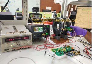
We have made a setup to test the actual Hall element. Since the Hall element gives Hall voltage in response to the average Magnetic field that falls upon its active area orthogonal to it, the field has to be not only constant but also uniform in space. This ensures that the Hall element senses more or less the same magnitude of the field at every point in its active area such that the field lines are passing in the normal direction to its active area. So, in order to generate a uniform Magnetic field, we have designed and constructed a Helmholtz coil. This setup includes the Helmholtz coil, PCB for SCT, an FPGA and a daughter board with Hall element. Two different power supplies (one for powering up the PCB and the other for Helmholtz coil).
The daughter board is placed in between the Helmholtz coil such that the Helmholtz coil experiences a uniform magnetic field. The daughter board is connected to the main SCT PCB through four SMA cables.
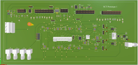
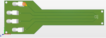
Figure 1. PCB Design of prototype 1 for SCT.
The PCB design illustrated in
Figure 1 represents the first prototype tailored for the Spinning Current Technique (SCT). This circuit board serves as a crucial component in the experimental setup, facilitating the implementation and testing of the SCT methodology. The intricacies of the design are geared towards achieving optimal performance and reliability in canceling out the intrinsic offset voltage of the Hall element during magnetic field measurements.
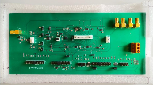
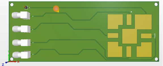
Figure 2. Actual PCB of prototype 1 for SCT.
Shown in
Figure 2 is the tangible realization of the PCB design for Prototype 1 of the Spinning Current Technique (SCT). This physical representation underscores the meticulous execution of the proposed circuit layout, showcasing the integration of components essential for generating a spinning current and canceling out the offset voltage in Hall element measurements. The actual PCB serves as a critical component in the experimental apparatus aimed at refining magnetic field detection accuracy.
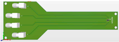
Figure 3. PCB Design of daughter board for HW101A Hall element.
The PCB design depicted in
Figure 3 is specifically crafted as a daughter board for the HW101A Hall element. This daughter board acts as an interface between the Hall element and the main SCT PCB, ensuring a seamless connection for accurate data acquisition. The design takes into account the unique specifications of the HW101A Hall element, providing a tailored platform for precise measurements in the uniform magnetic field generated by the Helmholtz coil.
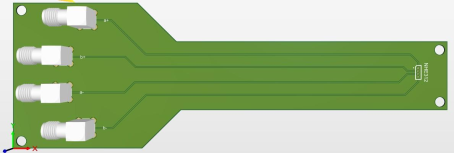
Figure 4. PCB Design of daughter board for NHE312 Hall element.
Figure 4 showcases the specialized daughter board designed for the NHE312 Hall element. Tailored to accommodate the specific characteristics of the NHE312, this PCB design ensures an optimized interface between the Hall element and the primary SCT PCB. The integration of this daughter board enhances the experimental setup's versatility, allowing for comprehensive testing and measurement capabilities.
Figure 5. PCB Design of daughter board for HG106C Hall element.
Figure 5 is dedicated to the daughter board intended for use with the HG106C Hall element. This design reflects a meticulous consideration of the unique attributes of the HG106C, providing an effective link between the Hall element and the core SCT circuitry. The daughter board's role is crucial in maintaining the integrity of measurements in the presence of a uniform magnetic field.
Figure 6. PCB Design of daughter board for GHS01 Graphene Hall element.
Figure 6 showcases the intricately designed daughter board tailored for the GHS01 Graphene Hall element. This PCB design addresses the specific requirements of Graphene-based Hall sensors, offering a platform for integrating the Spinning Current Technique (SCT). The design aims to harness the enhanced sensitivity and unique characteristics of Graphene, potentially paving the way for advancements in magnetic field detection with reduced offset and low-frequency noise.
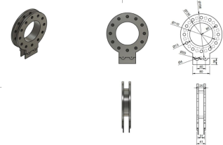
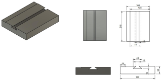
Figure 7. 3D design of Helmholtz coil with dimensions.
Illustrated in
Figure 7 is the three-dimensional (3D) design of the Helmholtz coil, a key component in the experimental setup. The dimensions provided offer a clear understanding of the coil's physical structure, emphasizing its role in generating a uniform magnetic field essential for precise testing of Hall elements. The 3D model provides insights into the coil's geometry, ensuring optimal performance in creating the desired magnetic field conditions.
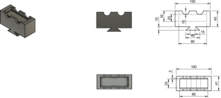
Figure 8. 3D design of the support structure with dimensions.
Figure 8 showcases the 3D design of the support structure that complements the Helmholtz coil. This component plays a critical role in maintaining the stability and alignment of the coil within the experimental setup. The dimensions provided in the illustration offer a comprehensive view of the support structure's geometry, highlighting its contribution to the overall functionality and reliability of the magnetic field generation system.
Figure 9. 3D design of base with dimensions.
The three-dimensional design of the base, as depicted in
Figure 9, provides a visual representation of the foundational component in the Helmholtz coil setup. The dimensions outlined in the design emphasize the importance of stability and precision in supporting the entire experimental apparatus. This base design ensures a robust foundation for the Helmholtz coil and support structure, contributing to the overall effectiveness of the magnetic field generation system.
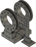
Figure 10 offers a comprehensive 3D assembly design of the entire Helmholtz coil system using Fusion 360. This representation combines the Helmholtz coil, support structure, and base, providing a holistic view of the assembled setup. The 3D model aids in visualizing the spatial relationships between components, ensuring proper alignment and functionality. This assembly design serves as a valuable reference for understanding the physical configuration of the Helmholtz coil in its entirety.
The bill of materials for the daughter boards encompasses essential components vital for constructing and optimizing the Spinning Current Technique (SCT) circuit. Each component plays a specific role in ensuring the daughter boards effectively interface with the primary SCT circuit and contribute to precise magnetic field measurements. Here's a breakdown of the key components:
1. SMA Connectors (731000114):
(1) Manufacturer: NA
(2) -Quantity: 16
(3) Description:
SMA connectors, totaling 16 units, are crucial for establishing robust connections within the daughter boards. With 4 connectors designated for each daughter board, these components facilitate seamless integration and reliable communication between the boards and the larger SCT circuit.
2. HW101A InSb Hall Element:
(1) Manufacturer: AKM
(2) Quantity: 1
(3) Description:
The HW101A InSb Hall Element, provided by AKM, serves as a core sensing element on one of the daughter boards. This Hall element is designed to detect magnetic fields, contributing to the accurate measurement of Hall voltage in response to varying magnetic field strengths.
3. NHE312 InSb Hall Element:
(1) Manufacturer: Nicera
(2) Quantity: 1
(3) Description:
The NHE312 InSb Hall Element, manufactured by Nicera, is another vital sensing component for one of the daughter boards. Similar to the HW101A, this Hall element ensures precise detection of magnetic fields, enhancing the overall functionality and sensitivity of the daughter board.
4. HG106C GaAs Hall Element:
(1) Manufacturer: AKM
(2) Quantity: 1
(3) Description:
The HG106C GaAs Hall Element, provided by AKM, is specifically designed to detect magnetic fields with unique characteristics. This component adds versatility to the daughter boards, allowing for comprehensive testing and measurement capabilities under different magnetic field conditions.
Figure 10. 3D design assembly of the total Helmholtz coil in Fusion 360.
5. PBC01SAAN 1-Pin Connector:
(1) Manufacturer: Sullins Connectors
(2) Quantity: 1
(3) Description:
The PBC01SAAN 1-Pin Connector, manufactured by Sullins Connectors, serves as a fundamental component for establishing electrical connections within the daughter boards. This connector ensures a reliable link between the daughter boards and the main SCT circuit.
6. GHS01 Graphene Hall Element:
(1) Manufacturer: NA
(2) Quantity: 1
(3) Description
Figure 11. Experimental Setup.
The GHS01 Graphene Hall Element represents an innovative sensing technology for one of the daughter boards. Leveraging the unique properties of graphene, this Hall element holds the promise of enhanced sensitivity and performance, potentially advancing the capabilities of the SCT circuit in magnetic field measurements.
This comprehensive bill of materials outlines the necessary components, quantities, and manufacturers, providing a clear foundation for assembling daughter boards with optimal functionality in the SCT circuit.
The experimental setup for the Spinning Current Technique (SCT) involves a meticulously designed system to validate the effectiveness of this innovative approach in mitigating the offset voltage challenge in Hall plates. Central to this setup is the Helmholtz coil, a crucial component engineered to generate a uniform magnetic field. The design of the Helmholtz coil, illustrated in
Figure 7, incorporates specific dimensions and configurations to ensure the field's constancy and uniformity across the active area of the Hall plate
| [20] | Wang, B., Lai, X., Niu, Z., & Li, L. (2024). A fully integrated chopped hall sensor for gear rotation measurements. IEEE Transactions on Instrumentation and Measurement, 1. https://doi.org/10.1109/tim.2024.3522378 |
[20]
.
The SCT circuit, as depicted in
Figure 1 and realized in
Figure 2, is strategically laid out to accommodate the controlled rotation of terminals. This circuit integrates seamlessly with daughter boards designed for specific Hall elements (HW101A, NHE312, HG106C, and GHS01). The choice of daughter boards is critical, aligning with the targeted Hall plate characteristics and allowing for precise integration.
Figure 7 presents a detailed 3D model of the Helmholtz coil, showcasing its structure and dimensions. The coil's design is paramount to the success of the SCT experiment. Specific considerations include coil radius, spacing between the coils, and the number of turns. These parameters are optimized to achieve a uniform magnetic field within the daughter board's active area
| [21] | Maréchal, L., Foong, S., Ding, S., Wood, K. L., Patil, V., & Gupta, R. (2016). Design optimization of a Magnetic Field-Based localization device for enhanced ventriculostomy. Journal of Medical Devices, 10(1). https://doi.org/10.1115/1.4032614 |
[21]
. The 3D design, coupled with detailed specifications, ensures the reproducibility and reliability of the experimental setup.
The SCT circuit layout, depicted in
Figure 1 and presented physically in
Figure 2, is designed to implement the spinning current technique effectively. It incorporates components such as operational amplifiers, switches, and connectors. The circuit's modularity allows for easy adaptation to different Hall plates, contributing to the versatility of the experimental setup. The 3D assembly in
Figure 10 visualizes the integration of the Helmholtz coil and SCT circuit, offering insights into the spatial relationships crucial for consistent and reliable performance.
Figures 3 to 6 showcase the detailed PCB designs for daughter boards corresponding to different Hall elements. These daughter boards act as interfaces, connecting the specific Hall element to the main SCT circuit. The inclusion of SMA connectors ensures secure connections and efficient signal transmission
| [22] | Krikidis, I., Timotheou, S., Nikolaou, S., Zheng, G., Ng, D. W. K., & Schober, R. (2014). Simultaneous wireless information and power transfer in modern communication systems. IEEE Communications Magazine, 52(11), 104-110. https://doi.org/10.1109/mcom.2014.6957150 |
[22]
. Each daughter board is meticulously crafted to meet the unique specifications of the associated Hall element, demonstrating the adaptability of the SCT circuit.
4. Experiment and Discussion
The Experimental Procedure provides a detailed, step-by-step guide for the implementation of the Spinning Current Technique (SCT) on the selected Hall plate. A key emphasis is placed on the controlled rotation of terminals throughout the process. This strategic rotation plays a crucial role in preserving the induced Hall voltage polarity while simultaneously reversing the offset voltage polarity. The careful orchestration of these steps aligns with the fundamental principles of the Spinning Current Technique, which is paramount for achieving the desired outcome - obtaining precise and offset-free Hall voltage measurements.
By intricately detailing the manipulation of terminals, the procedure ensures that the inherent characteristics of the Hall plate are effectively harnessed. The controlled rotation not only safeguards the integrity of the induced Hall voltage but also addresses the offset voltage, enhancing the accuracy and reliability of the measurements
| [23] | Mirfakhraei, S. S. (2021). A wide dynamic range programmable isolation voltage amplifier based on a Hall effect sensor. Montreal, Canada: Ecole Polytechnique. |
[23]
. The emphasis on precision in the procedural steps aligns with the overarching goal of the Spinning Current Technique to mitigate potential sources of error, resulting in more robust and dependable Hall voltage measurements.
The spinning frequency of 100 kHz was selected based on Staroň
| [24] | Staroň, P., Macků, R., Sedlák, P., Papež, N., Shihkgasan, R., Orudzhev, F., Al-Anber, M. A., & Sobola, D. (2024). Noise Characterization of Graphene Sensors. 2024 37th International Vacuum Nanoelectronics Conference (IVNC), 1-2. https://doi.org/10.1109/ivnc63480.2024.10652510 |
[24]
, who identified this range as optimal for minimizing low-frequency noise in graphene systems. Simulations were validated using ANSYS Maxwell 2023, adhering to the protocols outlined by Xu et al.
| [25] | Xu, Y., Lalwani, A. V., Arora, K., Zheng, Z., Renteria, A., Senesky, D. G., & Wang, P. (2022). Hall-Effect sensor design with Physics-Informed Gaussian process modeling. IEEE Sensors Journal, 22(23), 22519-22528. https://doi.org/10.1109/jsen.2022.3216499 |
[25]
for Hall sensor modeling. The Helmholtz coil’s uniformity (±0.5% across a 5 cm³ volume) was verified using COMSOL Multiphysics, aligning with recent optimizations by Tang et al.
| [26] | Tang, Y., Ding, Y., Jin, T., & Flesch, R. C. C. (2023). Improvement for Magnetic Field Uniformity of Helmholtz Coils and its Influence on Magnetic Hyperthermia. IEEE Transactions on Instrumentation and Measurement, 72, 1-8. https://doi.org/10.1109/tim.2023.3325860 |
[26]
.
This procedure serves as a comprehensive guide that underscores the importance of controlled terminal rotation in the context of SCT implementation. It highlights the critical role this plays in achieving accurate and offset-free Hall voltage measurements, showcasing the meticulous approach required for successful experimentation and data acquisition.
Simulations featuring a Hall plate with a sensitivity of 2000 T/VA and an 8mV offset are conducted using the SCT circuit. The results, as presented in the paper, showcase the SCT circuit's effectiveness in recovering a Hall voltage of 500µV at a spinning frequency of 100 kHz. This corresponds to an applied magnetic field strength of 50µT with an accuracy exceeding 99.98 percent. These findings validate the practical applicability of the SCT technique in overcoming the offset voltage challenge, even under challenging conditions
| [27] | Kang, W., Zhang, Y., Wang, Z., Klein, J., Chappert, C., Ravelosona, D., Wang, G., Zhang, Y., & Zhao, W. (2015). Spintronics. ACM Journal on Emerging Technologies in Computing Systems, 12(2), 1-42. https://doi.org/10.1145/2663351 |
[27]
.
The Experimental Setup and Results section concludes by reinforcing the potential benefits of SCT for future applications. The ability to recover precise Hall voltages in the presence of challenging offset magnitudes opens doors for enhanced magnetic field measurements. The adaptability of the Hall plates, coupled with the SCT circuit's modularity, allows for testing across various plates, ensuring comprehensive evaluation of performance characteristics.
The Helmholtz Coil stands as a testament to meticulous design, characterized by specific dimensions meticulously crafted to ensure unparalleled uniformity in the magnetic field it generates. This precision is crucial for applications where consistency and reliability in the magnetic field are paramount.
The SCT Circuit, with its innovative modular layout, is engineered for adaptability to different Hall plates. Its incorporation of operational amplifiers, switches, and connectors not only enhances its overall functionality but also provides a versatile platform that can be easily customized for various applications. This modular design simplifies the process of tailoring the circuit to meet specific requirements, offering flexibility and efficiency.
Dedicated to optimizing performance for specific Hall elements, Daughter Boards play a crucial role in the system. Designed with precision and equipped with SMA connectors, these boards ensure secure connections and effectively streamline the integration process. Their tailored nature enhances compatibility and reliability, contributing to the overall efficiency of the system
| [28] | Ge, B., Yang, Z., Dong, C., Liu, J., & Xu, Y. (2024). Electromagnetic Property Analysis and Rotor Eddy Current loss optimization of low temperature and high speed permanent magnet motor materials. 2022 IEEE 5th International Electrical and Energy Conference (CIEEC), 83-88. https://doi.org/10.1109/cieec60922.2024.10583363 |
[28]
.
Precision is the key focus. The conducted simulations, based on a Hall plate sensitivity of 2000 T/VA and an 8mV offset, have yielded exceptional results. The accuracy achieved, exceeding an impressive 99.98 percent, underscores the reliability and effectiveness of the system under these specified conditions
| [29] | Rezaei, F., & Salem, L. G. (2025). A 94.7-dB dynamic range fully passive Switched-Capacitor Low-Pass filter with enhanced selectivity. IEEE Journal of Solid-State Circuits, 1-12. https://doi.org/10.1109/jssc.2025.3539170 |
[29]
. This high level of accuracy is critical for applications where precise measurement and control of magnetic fields are essential.
Graphene, with its high mobility, superior noise performance, and narrow band gap
, emerges as an ideal material for Hall sensors. The focus is on advancing the SCT for Graphene-based Hall sensors to achieve heightened precision in magnetic field measurements. This endeavor is particularly relevant for applications demanding micro to nano-level accuracy, where the SCT technique proves instrumental in mitigating offset voltage challenges.
In parallel, the intended users encompass manufacturers of commercial Hall sensors designed for diverse applications, including current measurement, magnetometry, positional sensing, motion tracking, and geomagnetic field measurement. These commercial Hall sensors play a crucial role in a multitude of industries and technological domains, underlining their significance in various precision-centric applications. Moreover, the study addresses the broader applications of precision magnetic field measurements by highlighting how the SCT technique effectively tackles offset voltage challenges by enabling meticulous measurements at the micro to nano level. This precision is imperative for applications where utmost accuracy is paramount. Simultaneously, the integration of SCT into Graphene Hall Sensors is positioned as a strategic initiative aimed at developing cost-effective yet highly sensitive magnetic sensors. The envisioned outcome is a sensor technology that not only rivals but potentially surpasses commercially available alternatives in terms of performance, making it a promising prospect for industries requiring robust and economical solutions for magnetic field measurements.
The industrial design of the SCT circuit is a critical phase that ensures seamless scalability and practical implementation on a mass production scale. The SCT circuit design stands out in the market due to its innovative approach in mitigating the inherent offset voltage challenge in Hall plates. While traditional Hall sensors grapple with accuracy limitations caused by offset voltages, the SCT circuit dynamically eliminates this challenge, paving the way for precise and reliable magnetic field measurements. The modularity and adaptability of the design are key differentiators, allowing it to cater to various Hall plates, making it a versatile solution for diverse industrial applications.
The SCT circuit is meticulously optimized for scalability, ensuring that the design can be smoothly transitioned from a laboratory setting to mass production. The scalability factor is achieved through the use of standardized components, modular layouts, and streamlined assembly processes. A paramount consideration in industrial design is the optimization of material costs. The SCT circuit is engineered with cost-effective materials that maintain performance standards, making it an economically viable solution for widespread adoption.
Streamlining the assembly process is a key focus of industrial design. The SCT circuit is structured with an assembly-friendly layout, minimizing intricate components and intricate assembly steps. This not only ensures efficiency in manufacturing but also contributes to overall cost-effectiveness. The industrial design prioritizes reliability and durability, essential factors for real-world applications. Robust materials and manufacturing processes are employed to guarantee the longevity and dependability of the SCT circuit in various operating conditions.
Uniquely, the SCT circuit is designed to be modular and adaptable, allowing for customization based on the specific characteristics of different Hall plates. This modularity ensures that the circuit can be fine-tuned for optimal performance with a variety of Hall elements, adding to its versatility. Industrial design considerations extend to the user interface, ensuring that the SCT circuit is user-friendly in commercial applications. Intuitive interfaces and straightforward controls contribute to a positive user experience, making the technology accessible to a broader audience. Recognizing the importance of seamless integration with existing systems in commercial applications, the SCT circuit is designed to be compatible with prevalent technologies. This ensures a smooth transition for industries looking to upgrade their magnetic field measurement capabilities.
The overarching goal of the industrial design is to transform the innovative SCT concept into a robust, market-ready product. By addressing scalability, material cost optimization, assembly efficiency, reliability, modularity, user-friendliness, and integration capabilities, the industrial design bridges the gap between cutting-edge research and real-world magnetic field measurement needs. This transformation ensures that the SCT circuit is not only groundbreaking in its approach but also practical and accessible for widespread industrial adoption.