Finding new efficient low-cost methods to use CMOS technology is one of the main topics in this area due to the physical limitations of the present methods. The researchers are looking to find new solutions to overcome VLSI problems such as large area, high power consumption, low speed, and electrical current issues. Quantum-dot cellular automata is a new nano-scale technology that has overcome the limits of metal oxide technology and is considered as an advanced method in digital circuit designs. QCA has attracted the attention of many researchers due to its special features such as power consumption, high-speed computing operations, and small dimensions. Besides, the counter is a module that has wide applications in digital systems. In this study, an optimized counter has been proposed in Quantum-dot cellular automata which has utilized T Flip-Flop and improved the cell number and area parameters. The design of the proposed circuit has employed 108 cells. The simulation results of the circuit show 0.1 μm2 of area occupation. Also, the delay of circuit is 4.25 clock periods. This design has improved the cell number and area by 22% and 39%, respectively. The power or Complexity has reduced by 22% compare to the best prior design.
| Published in | Journal of Electrical and Electronic Engineering (Volume 13, Issue 1) |
| DOI | 10.11648/j.jeee.20251301.14 |
| Page(s) | 40-45 |
| Creative Commons |
This is an Open Access article, distributed under the terms of the Creative Commons Attribution 4.0 International License (http://creativecommons.org/licenses/by/4.0/), which permits unrestricted use, distribution and reproduction in any medium or format, provided the original work is properly cited. |
| Copyright |
Copyright © The Author(s), 2025. Published by Science Publishing Group |
Digital Circuit Design, Quantum-Dot Cellular Automata, T Flip-Flop, Three Bit Counter
Percent of improvement [14] | Proposed | [14] | [13] | [12] | [11] | [10] | [9] | Measurement metrics |
|---|---|---|---|---|---|---|---|---|
22% | 108 | 140 | 174 | 196 | 238 | 244 | 616 | Cell Count (cell) |
39% | 0.1 | 0.165 | 0.194 | 0.218 | 0.36 | 0.346 | 1.2 | Area (μm2) |
0% | 4.25 | 2 | 3 | 2 | 4.25 | 4.25 | 5 | Delay (clock) |
22% | 108 | 140 | 174 | 196 | 238 | 244 | 616 | Complexity (cell) |
Design | Average energy dissipation per cycle (Avg-Ebath) | Total energy dissipation (Sum-Ebath) | Our circuit improvement |
|---|---|---|---|
[9] | 23.72 e-0.03 | 23.53 e-0.02 | 89% |
[10] | 6.84 e-0.03 | 7.53 e-0.02 | 65% |
[11] | 6.03 e-0.03 | 6.63 e-0.02 | 60% |
[12] | 5.34 e-0.03 | 5.87 e-0.02 | 55% |
[13] | 3.08 e-0.03 | 3.39 e-0.02 | 23% |
[14] | 3.39 e-0.03 | 3.73 e-0.02 | 30% |
[proposed] | 2.37 e-0.03 | 2.61 e-0.02 | -------- |
CMOS | Complementary Metal Oxide Semiconductor |
QCA | Quantum-dot Cellular Automata |
P | Polarization |
| [1] | M. Zahmatkesh, S. Tabrizchi, S. Mohammadyan, K. Navi, N. Bagherzadeh, Robust Coplanar Full Adder Based on Novel Inverter in Quantum Cellular Automata, International Journal of Theoretical Physics, 58 (2019) 639-655. |
| [2] | G. E. Moore, Cramming more components onto integrated circuits, in, McGraw-Hill New York, NY, USA:, 1965. |
| [3] | R. Chakrabarty, D. K. Mahato, A. Banerjee, S. Choudhuri, M. Dey, N. Mandal, A novel design of flip-flop circuits using quantum dot cellular automata (QCA), in: 2018 IEEE 8th Annual Computing and Communication Workshop and Conference (CCWC), IEEE, 2018, pp. 408-414. |
| [4] | H. Cho, E. E. Swartzlander, Adder and multiplier design in quantum-dot cellular automata, IEEE Transactions on Computers, 58 (2009) 721-727. |
| [5] | C. Lent, P. Tougaw, W. Porod and GH Bernstein, Quantum Cellular Automata, Nanotechnology, 4 (1993) 49-57. |
| [6] | K. Kim, K. Wu, R. Karri, Quantum-dot cellular automata design guideline, IEICE Transactions on Fundamentals of Electronics, Communications and Computer Sciences, 89 (2006) 1607-1614. |
| [7] | M. Beigh, M. Mustafa, Design and analysis of a simple D flip-flop based sequential logic circuits for QCA implementation, in: 2014 International Conference on Computing for Sustainable Global Development (INDIACom), IEEE, 2014, pp. 536-540. |
| [8] | C. S. Lent, P. D. Tougaw, W. Porod, Quantum cellular automata: the physics of computing with arrays of quantum dot molecules, in: Proceedings Workshop on Physics and Computation. PhysComp'94, IEEE, 1994, pp. 5-13. |
| [9] | X. Yang, L. Cai, X. Zhao, N. Zhang, Design and simulation of sequential circuits in quantum-dot cellular automata: falling edge-triggered flip-flop and counter study, Microelectronics Journal, 41 (2010) 56-63. |
| [10] | K. S. Bhavani, V. Alinvinisha, Utilization of QCA based T Flip flop to design Counters, in: 2015 International Conference on Innovations in Information, Embedded and Communication Systems (ICIIECS), IEEE, 2015, pp. 1-6. |
| [11] | S. Angizi, M. H. Moaiyeri, S. Farrokhi, K. Navi, N. Bagherzadeh, Designing quantum-dot cellular automata counters with energy consumption analysis, Microprocessors and Microsystems, 39 (2015) 512-520. |
| [12] | M. Abutaleb, Robust and efficient quantum-dot cellular automata synchronous counters, Microelectronics Journal, 61 (2017) 6-14. |
| [13] | Z. Amirzadeh, M. Gholami, Counters Designs with Minimum Number of Cells and Area in the Quantum-Dot Cellular Automata Technology, International Journal of Theoretical Physics, (2019) 1-18. |
| [14] | A. H. Majeed, E. Alkaldy, M. S. bin Zainal, B. M. Nor, Synchronous counter design using novel level sensitive T-FF in QCA technology, Journal of Low Power Electronics and Applications, 9 (2019) 27. |
| [15] | C. S. Lent, P. D. Tougaw, A device architecture for computing with quantum dots, Proceedings of the IEEE, 85 (1997) 541-557. |
| [16] | F. Lombardi, J. Huang, Design and test of digital circuits by quantum-dot cellular automata, Artech House, Inc., 2007. |
| [17] | C. S. Lent, M. Liu, Y. Lu, Bennett clocking of quantum-dot cellular automata and the limits to binary logic scaling, Nanotechnology, 17 (2006) 4240. |
| [18] | R. Ravichandran, N. Ladiwala, J. Nguyen, M. Niemier, S. K. Lim, Automatic cell placement for quantum-dot cellular automata, in: Proceedings of the 14th ACM Great Lakes symposium on VLSI, ACM, 2004, pp. 332-337. |
| [19] | B. Bilal, S. Ahmed, V. Kakkar, Multifunction reversbile logic gate: Logic synthesis and design implementation in QCA, in: 2017 International Conference on Computing, Communication and Automation (ICCCA), IEEE, 2017, pp. 1385-1390. |
| [20] | J. Mohammadi, M. Zare, Molaei M, M. Maadani, Low-cost three-bit counter design in quantum-dot cellular automata technology. IETE Journal of Research. 2023 Oct 31; 69(10): 6794-801. |
| [21] | C. S. Lent, B. Isaksen, Clocked molecular quantum-dot cellular automata, IEEE Transactions on Electron Devices, 50 (2003) 1890-1896. |
| [22] | V. Vankamamidi, M. Ottavi, F. Lombardi, Clocking and cell placement for QCA, in: 2006 Sixth IEEE Conference on Nanotechnology, IEEE, 2006, pp. 343-346. |
| [23] | J. Maharaj, S. Muthurathinam, Effective RCA design using quantum dot cellular automata, Microprocessors and Microsystems, 73 (2020) 102964. |
| [24] | L. A. Lim, A. Ghazali, S. C. T. Yan, C. C. Fat, Sequential circuit design using quantum-dot cellular automata (qca), in: 2012 IEEE International Conference on Circuits and Systems (ICCAS), IEEE, 2012, pp. 162-167. |
| [25] | K. Walus, T. J. Dysart, G. A. Jullien, R. A. Budiman, QCADesigner: A rapid design and simulation tool for quantum-dot cellular automata, IEEE transactions on nanotechnology, 3 (2004) 26-31. |
| [26] | M. Patidar, N. Gupta, An efficient design of edge-triggered synchronous memory element using quantum dot cellular automata with optimized energy dissipation, Journal of Computational Electronics, (2020) 1-14. |
APA Style
Mohammadi, J., Zare, M., Molaei, M. (2025). Optimized Three Bit Counter Employing T Flip-Flop in Quantum-Dot Cellular Automata Technology. Journal of Electrical and Electronic Engineering, 13(1), 40-45. https://doi.org/10.11648/j.jeee.20251301.14
ACS Style
Mohammadi, J.; Zare, M.; Molaei, M. Optimized Three Bit Counter Employing T Flip-Flop in Quantum-Dot Cellular Automata Technology. J. Electr. Electron. Eng. 2025, 13(1), 40-45. doi: 10.11648/j.jeee.20251301.14
@article{10.11648/j.jeee.20251301.14,
  author = {Javad Mohammadi and Mahdi Zare and Masoumeh Molaei},
  title = {Optimized Three Bit Counter Employing T Flip-Flop in Quantum-Dot Cellular Automata Technology},
  journal = {Journal of Electrical and Electronic Engineering},
  volume = {13},
  number = {1},
  pages = {40-45},
  doi = {10.11648/j.jeee.20251301.14},
  url = {https://doi.org/10.11648/j.jeee.20251301.14},
  eprint = {https://article.sciencepublishinggroup.com/pdf/10.11648.j.jeee.20251301.14},
  abstract = {Finding new efficient low-cost methods to use CMOS technology is one of the main topics in this area due to the physical limitations of the present methods. The researchers are looking to find new solutions to overcome VLSI problems such as large area, high power consumption, low speed, and electrical current issues. Quantum-dot cellular automata is a new nano-scale technology that has overcome the limits of metal oxide technology and is considered as an advanced method in digital circuit designs. QCA has attracted the attention of many researchers due to its special features such as power consumption, high-speed computing operations, and small dimensions. Besides, the counter is a module that has wide applications in digital systems. In this study, an optimized counter has been proposed in Quantum-dot cellular automata which has utilized T Flip-Flop and improved the cell number and area parameters. The design of the proposed circuit has employed 108 cells. The simulation results of the circuit show 0.1 μm2 of area occupation. Also, the delay of circuit is 4.25 clock periods. This design has improved the cell number and area by 22% and 39%, respectively. The power or Complexity has reduced by 22% compare to the best prior design.},
 year = {2025}
}
TY  - JOUR
T1  - Optimized Three Bit Counter Employing T Flip-Flop in Quantum-Dot Cellular Automata Technology
AU  - Javad Mohammadi
AU  - Mahdi Zare
AU  - Masoumeh Molaei
Y1  - 2025/02/10
PY  - 2025
N1  - https://doi.org/10.11648/j.jeee.20251301.14
DO  - 10.11648/j.jeee.20251301.14
T2  - Journal of Electrical and Electronic Engineering
JF  - Journal of Electrical and Electronic Engineering
JO  - Journal of Electrical and Electronic Engineering
SP  - 40
EP  - 45
PB  - Science Publishing Group
SN  - 2329-1605
UR  - https://doi.org/10.11648/j.jeee.20251301.14
AB  - Finding new efficient low-cost methods to use CMOS technology is one of the main topics in this area due to the physical limitations of the present methods. The researchers are looking to find new solutions to overcome VLSI problems such as large area, high power consumption, low speed, and electrical current issues. Quantum-dot cellular automata is a new nano-scale technology that has overcome the limits of metal oxide technology and is considered as an advanced method in digital circuit designs. QCA has attracted the attention of many researchers due to its special features such as power consumption, high-speed computing operations, and small dimensions. Besides, the counter is a module that has wide applications in digital systems. In this study, an optimized counter has been proposed in Quantum-dot cellular automata which has utilized T Flip-Flop and improved the cell number and area parameters. The design of the proposed circuit has employed 108 cells. The simulation results of the circuit show 0.1 μm2 of area occupation. Also, the delay of circuit is 4.25 clock periods. This design has improved the cell number and area by 22% and 39%, respectively. The power or Complexity has reduced by 22% compare to the best prior design.
VL  - 13
IS  - 1
ER  -
Department of Electronic Engineering, Shahr-e-Qods Branch, Islamic Azad University, Tehran, Iran

Figure 1. Representation of the QCA cell.
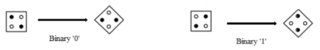
Figure 2. Electron arrangement for 45 degree phase 90 degree phase.
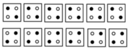
Figure 3. Formation of a wire using quantum dot cells.
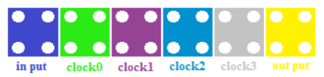
Figure 4. Color of input, output and clock cells.
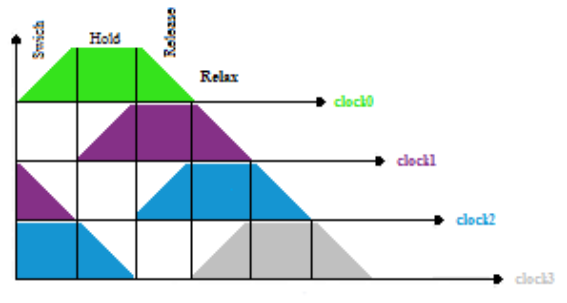
Figure 5. Phase plots in each clock.
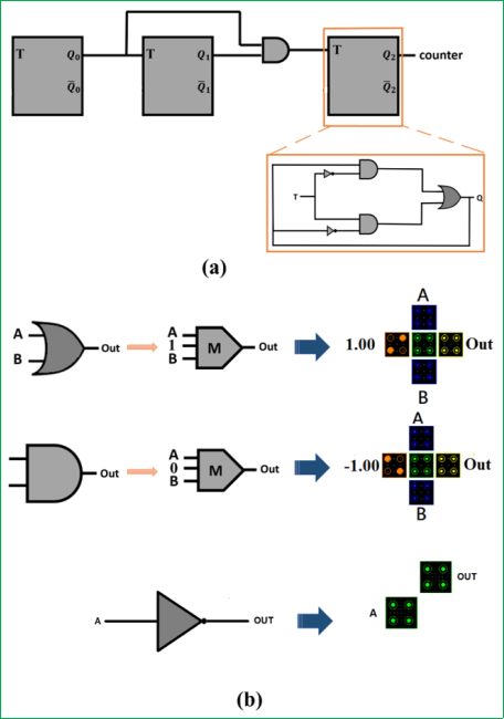
Figure 6. (a) Block diagram of 3-bits counter using T-flip flop. (b) Design of ‘AND’ and ‘OR’ gates.
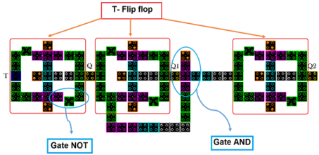
Figure 7. The structure of the proposed 3 bit counter.
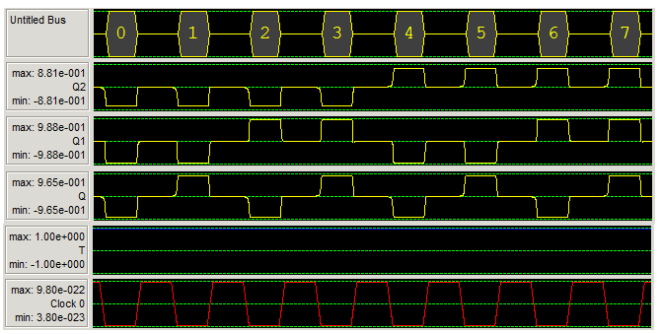
Figure 8. Simulation of the proposed 3 bit counter.
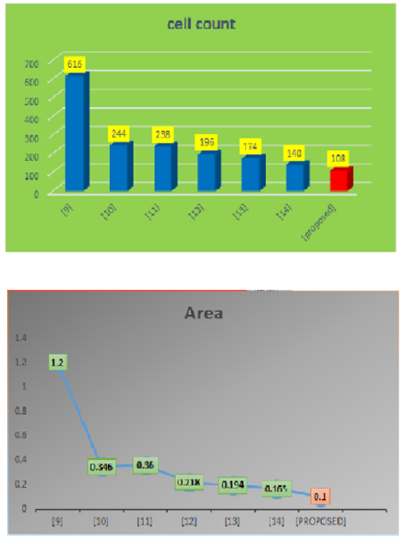
Figure 9. (a) Comparison of the proposed circuit cells number with the previous researches. (b) area of our study and the previous researches.
Information