Cantilever balconies are widely used in modern buildings due to their architectural flexibility and efficient use of space. However, their structural performance is highly sensitive to environmental loading because their bending resistance is concentrated at the fixed support. In real service conditions, these structures are simultaneously subjected to static loads, wind-induced aerodynamic forces, seasonal thermal effects, and seismic ground acceleration. Most conventional analyses treat these effects independently, which may underestimate cumulative deflection and lead to inaccurate serviceability predictions. This study develops a unified mathematical model to quantify the total tip deflection of a cantilever balcony subjected to combined static, wind, thermal, and seismic loading. The formulation is based on Euler–Bernoulli beam theory and linear elasticity assumptions. Closed-form analytical expressions are derived for each loading component and integrated using the principle of superposition to obtain a compact total deflection equation. Numerical simulations are performed for aluminum, steel, reinforced concrete, and carbon fiber composites under representative environmental conditions. Results show that thermal effects become dominant in high-temperature environments for materials with large coefficients of thermal expansion, while seismic effects become significant in regions with high peak ground acceleration. Among the materials considered, carbon fiber composites consistently exhibit the smallest total deflection due to their high stiffness and low thermal sensitivity, while reinforced concrete shows the largest deformation due to its lower elastic modulus. The proposed model provides a mathematically consistent framework for evaluating cantilever balcony performance under multi-hazard environmental loading and offers a useful decision-support tool for preliminary structural design and material selection.
| Published in | Pure and Applied Mathematics Journal (Volume 15, Issue 3) |
| DOI | 10.11648/j.pamj.20261503.11 |
| Page(s) | 35-44 |
| Creative Commons |
This is an Open Access article, distributed under the terms of the Creative Commons Attribution 4.0 International License (http://creativecommons.org/licenses/by/4.0/), which permits unrestricted use, distribution and reproduction in any medium or format, provided the original work is properly cited. |
| Copyright |
Copyright © The Author(s), 2026. Published by Science Publishing Group |
Cantilever Balcony, Euler–Bernoulli Beam, Wind Loading, Thermal Expansion, Peak Ground Acceleration, Multi-hazard Modeling
Material | E(Pa) | Α(1/°C) |
|---|---|---|
Aluminum | 1.7×10¹¹ | 2.3×10⁻⁵ |
Steel | 2.0×10¹¹ | 1.2×10⁻⁵ |
Reinforced Concrete | 3.0×10¹⁰ | 1.0×10⁻⁵ |
Carbon Fiber | 2.3×10¹¹ | 0.3×10⁻⁵ |
Location | Season | Avg Temp (°C) | Max Temp (°C) | Avg Wind (m/s) | PGA (g) |
|---|---|---|---|---|---|
Nairobi (Kenya) | Hot-Dry | 23.5 | 28.0 | 3.5 | 0.06 |
Long Rains | 22.5 | 27.0 | 3.8 | 0.08 | |
Cool-Dry | 20.0 | 24.0 | 3.2 | 0.08 | |
Short Rains | 22.0 | 26.5 | 3.6 | 0.07 | |
Doha (Qatar) | Winter | 18.5 | 24.0 | 3.9 | 0.05 |
Spring | 28.0 | 36.0 | 4.3 | 0.06 | |
Summer | 36.5 | 44.0 | 4.6 | 0.06 | |
Autumn | 29.0 | 37.0 | 4.2 | 0.05 | |
Las Vegas (USA) | Winter | 9.3 | 15.6 | 3.5 | 0.10 |
Spring | 21.6 | 31.0 | 4.0 | 0.20 | |
Summer | 34.6 | 44.5 | 4.6 | 0.30 | |
Autumn | 22.3 | 32.2 | 3.8 | 0.20 |
Scenario | Material | δtotal (mm) |
|---|---|---|
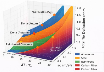
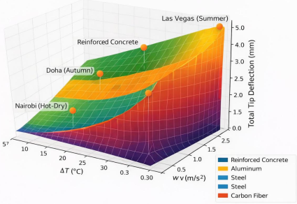
Nairobi(Hot-Dry) | Aluminum | 0.237 |
Nairobi(Hot-Dry) | Steel | 0.201 |
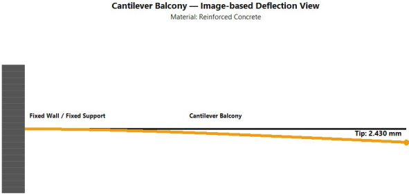
Nairobi(Hot-Dry) | Reinforced Concrete | 1.343 |
Nairobi(Hot-Dry) | Carbon Fiber | 0.175 |
Doha(Autumn) | Aluminum | 0.233 |
Doha(Autumn) | Steel | 0.198 |
Doha(Autumn) | Reinforced Concrete | 1.321 |
Doha(Autumn) | Carbon Fiber | 0.172 |
Las Vegas(Summer) | Aluminum | 0.337 |
Las Vegas(Summer) | Steel | 0.286 |
Las Vegas(Summer) | Reinforced Concrete | 1.910 |
Las Vegas(Summer) | Carbon Fiber | 0.249 |
Avg | Average |
CRC | Chemical Rubber Company |
meff | Effective Mass |
keff | Effective Stiffness |
PGA | Peak Ground Acceleration |
SDOF | Single Degree of Freedom |
USGS | Unites States Geological Survey |
NOAA | National Oceanic and Atmospheric Administration |
| [1] | Chopra, A. K. Dynamics of Structures: Theory and Applications to Earthquake Engineering. Journal of Structural Engineering. 2002, 128(6). |
| [2] | Ghadiri., M., et al. Thermomechanical vibration of orthotropic cantilever and propped cantilever nanoplate using generalized differential quadrature method. Advanced Material and Structures. 2017, 24(8) 636-646. |
| [3] | Gonzalez., et al Nonlinear response of Cantilever Beam due to large Geometric deformations. Experimental validation. Journal of Mechanical engineering. 2026, 62(3) 187-196. |
| [4] | Hassan, R. H. M. Structural analysis and detailing in architecture. Fundamental concepts and Principles. (2025) |
| [5] | Holmes, J. D. Wind Loading of Structures. CRC Press (2015). |
| [6] | Kramer, S. L. and Stewart J. P. Geotechnical Earthquake Engineering. CRC Press (2024). |
| [7] | Mohammed J. K. Recent Advances in Approximate methods for predicting nonlinear vibrations in Cantilever beams and plates. A review of Eurasian. Journal of Science and Engineering.2025, 11(2), 1555-78. |
| [8] | National Oceanic and Atmospheric Administration. Climate Data Online (2023). Available at: |
| [9] | Pe`rez-Carramin`ana, C., et al Influence of balcony thermal bridge on energy efficiency of dwellings in warm semi-arid dry Mediterranean climate. Buildings. 2024 14(3) 703. |
| [10] | Simiu, E. and Yeo, D. Advances in the design of high-rise structures by the wind tunnel procedure. Conceptual framework wind structure. 2015, 21(5) 489-503. |
| [11] | Timoshenko, S. Strength of Materials. D. Van Nostrand Company, Incorporated. 1961. |
| [12] | Touz`e, C. and Olivier Thomas. Reduced-order Modeling for Cantilever beam subjected to harmonic forcing in Euromech 457. Nonlinear modes of vibrating systems. |
| [13] | United States Geological Survey. Seismic hazard maps for Nevada (2024). Available at: |
| [14] | Zhong, J., et al. Recent advances in modeling turbulent wind flow at pedestrian level in the built environment. Architectural Intelligence. 2022, 1(1). 5. |
APA Style
Oketch, T. L., Obiero, B. A. O., Bii, A. (2026). Mathematical Modeling of Integrated Wind, Thermal, and Tectonic Stress Analysis on Cantilever Balconies Using Ordinary Differential Equations. Pure and Applied Mathematics Journal, 15(3), 35-44. https://doi.org/10.11648/j.pamj.20261503.11
ACS Style
Oketch, T. L.; Obiero, B. A. O.; Bii, A. Mathematical Modeling of Integrated Wind, Thermal, and Tectonic Stress Analysis on Cantilever Balconies Using Ordinary Differential Equations. Pure Appl. Math. J. 2026, 15(3), 35-44. doi: 10.11648/j.pamj.20261503.11
@article{10.11648/j.pamj.20261503.11,
  author = {Titus Leonard Oketch and Beatrice Adhiambo Odero Obiero and Albert Bii},
  title = {Mathematical Modeling of Integrated Wind, Thermal, and Tectonic Stress Analysis on Cantilever Balconies Using Ordinary Differential Equations},
  journal = {Pure and Applied Mathematics Journal},
  volume = {15},
  number = {3},
  pages = {35-44},
  doi = {10.11648/j.pamj.20261503.11},
  url = {https://doi.org/10.11648/j.pamj.20261503.11},
  eprint = {https://article.sciencepublishinggroup.com/pdf/10.11648.j.pamj.20261503.11},
  abstract = {Cantilever balconies are widely used in modern buildings due to their architectural flexibility and efficient use of space. However, their structural performance is highly sensitive to environmental loading because their bending resistance is concentrated at the fixed support. In real service conditions, these structures are simultaneously subjected to static loads, wind-induced aerodynamic forces, seasonal thermal effects, and seismic ground acceleration. Most conventional analyses treat these effects independently, which may underestimate cumulative deflection and lead to inaccurate serviceability predictions. This study develops a unified mathematical model to quantify the total tip deflection of a cantilever balcony subjected to combined static, wind, thermal, and seismic loading. The formulation is based on Euler–Bernoulli beam theory and linear elasticity assumptions. Closed-form analytical expressions are derived for each loading component and integrated using the principle of superposition to obtain a compact total deflection equation. Numerical simulations are performed for aluminum, steel, reinforced concrete, and carbon fiber composites under representative environmental conditions. Results show that thermal effects become dominant in high-temperature environments for materials with large coefficients of thermal expansion, while seismic effects become significant in regions with high peak ground acceleration. Among the materials considered, carbon fiber composites consistently exhibit the smallest total deflection due to their high stiffness and low thermal sensitivity, while reinforced concrete shows the largest deformation due to its lower elastic modulus. The proposed model provides a mathematically consistent framework for evaluating cantilever balcony performance under multi-hazard environmental loading and offers a useful decision-support tool for preliminary structural design and material selection.},
 year = {2026}
}
TY  - JOUR
T1  - Mathematical Modeling of Integrated Wind, Thermal, and Tectonic Stress Analysis on Cantilever Balconies Using Ordinary Differential Equations
AU  - Titus Leonard Oketch
AU  - Beatrice Adhiambo Odero Obiero
AU  - Albert Bii
Y1  - 2026/05/11
PY  - 2026
N1  - https://doi.org/10.11648/j.pamj.20261503.11
DO  - 10.11648/j.pamj.20261503.11
T2  - Pure and Applied Mathematics Journal
JF  - Pure and Applied Mathematics Journal
JO  - Pure and Applied Mathematics Journal
SP  - 35
EP  - 44
PB  - Science Publishing Group
SN  - 2326-9812
UR  - https://doi.org/10.11648/j.pamj.20261503.11
AB  - Cantilever balconies are widely used in modern buildings due to their architectural flexibility and efficient use of space. However, their structural performance is highly sensitive to environmental loading because their bending resistance is concentrated at the fixed support. In real service conditions, these structures are simultaneously subjected to static loads, wind-induced aerodynamic forces, seasonal thermal effects, and seismic ground acceleration. Most conventional analyses treat these effects independently, which may underestimate cumulative deflection and lead to inaccurate serviceability predictions. This study develops a unified mathematical model to quantify the total tip deflection of a cantilever balcony subjected to combined static, wind, thermal, and seismic loading. The formulation is based on Euler–Bernoulli beam theory and linear elasticity assumptions. Closed-form analytical expressions are derived for each loading component and integrated using the principle of superposition to obtain a compact total deflection equation. Numerical simulations are performed for aluminum, steel, reinforced concrete, and carbon fiber composites under representative environmental conditions. Results show that thermal effects become dominant in high-temperature environments for materials with large coefficients of thermal expansion, while seismic effects become significant in regions with high peak ground acceleration. Among the materials considered, carbon fiber composites consistently exhibit the smallest total deflection due to their high stiffness and low thermal sensitivity, while reinforced concrete shows the largest deformation due to its lower elastic modulus. The proposed model provides a mathematically consistent framework for evaluating cantilever balcony performance under multi-hazard environmental loading and offers a useful decision-support tool for preliminary structural design and material selection.
VL  - 15
IS  - 3
ER  -
Department of Mathematics Statistics and Computing, Rongo University, Rongo, Kenya
Department of Mathematics Statistics and Computing, Rongo University, Rongo, Kenya
Department of mathematics and Computer Science, University of Eldoret, Eldoret, Kenya
Information