Abstract
Cu-Cr alloys are widely used to extend the life of the copper mould tube for continuous casting machine (CCM) because of good wear and heat resistance. Current study is focused on the improvement of Cr yield under the atmospheric induction melting rather than vacuum melting of Cu-Cr alloys. The melting temperature was determined on the thermodynamic analysis of Cr redox process and metallic Cr rather than Cu-Cr intermediate alloy was used for alloying. The optimum conditions are melting temperature 1350℃, lump size 30 mm and holding period 30-35 min, witha chromium yield of 90%. At high temperatures, water vapor dissociates into oxygen and hydrogen, which increasesoxide inclusion and gas porosity. Since carbon from a graphite crucible reacts with Cr, it is preferable to use a zirconia or magnesia crucibles. It is considered positive to add magnesium to the copper-chromium alloy because magnesium is highly deoxidation-resistant and can improve the physical and mechanical properties of the alloy.
|
Published in
|
Science Discovery Physics (Volume 1, Issue 1)
|
|
DOI
|
10.11648/j.sdp.20260101.16
|
|
Page(s)
|
62-69 |
|
Creative Commons
|

This is an Open Access article, distributed under the terms of the Creative Commons Attribution 4.0 International License (http://creativecommons.org/licenses/by/4.0/), which permits unrestricted use, distribution and reproduction in any medium or format, provided the original work is properly cited.
|
|
Copyright
|
Copyright © The Author(s), 2026. Published by Science Publishing Group
|
Keywords
Cu-Cr alloys, Cr Yield, Atmospheric Induction Melting, Crystllizer
1. Introduction
Since Cu-Cr alloys have high thermal conductivity and abrasive resistance, they are widely used in various fields such as contact materials, crystallizer copper mould tube, electric conductors, wire-welding electrodes, etc
| [1] | Filipe C, Gisele L. Effect of ECAP processing on distribution of second phase particles, hardness and electrical conductivity of Cu−0.81Cr−0.07Zr alloy Trans. Nonferrous Met. Soc. China. 32(2022) 217−232. |
| [2] | Fang H, Liu P. Effect of Ti addition on the microstructure and properties of Cu–Cr alloy. Mater. Sci. Technol. 37(2021) 672–681. |
| [3] | Wang Y, Qu J, Wang, X. Effects of Y addition on the microstructure, properties and softening resistance of Cu-Cr alloy. J. Alloys Compd. 902(2022) 163816. |
[1-3]
.
The technical standards for chemical composition of crystallizer copper mould tube for CCM are shown in
Table 1 .
Many studies have been carried out on the melting process, microstructure, strengthening effect and heat treatment of these alloys to improve the physical and mechanical properties
| [5] | Ma M, Xiao Z, Meng X. Effects of trace calcium and strontium on microstructure and properties of Cu-Cr alloys. J. Mater. Sci. Technol. 112(2022) 11–23. |
| [6] | Peng, H, Xie, W, Chen, H. Effect of micro-alloying element Ti on mechanical properties of Cu–Cr alloy. J. Alloys Compd. 85(22021) 157004–157013. |
| [7] | Li J, Ding H. Effect of Cr and Sn additions on microstructure, mechanical-electrical properties and softening resistance of Cu–Cr–Sn alloy. Mater. Sci. Eng. A. 802(2021) 140628–140637. |
| [8] | Sun Y, Peng L, Huang G. Effects of Mg addition on the microstructure and softening resistance of Cu–Cr alloys. Mater. Sci. Eng. A. 776 (2020) 139009–139019. |
| [9] | Yang X. H, Wang C. D, Yang L. Effects of Nb addition and different cooling methods on microstructures and properties of Cu-Cr Alloys. J. Mater. Eng. Perform. 29(2020) 5008–5017. |
| [10] | Yang Y, Kuang G, Li R. Optimizing the electrical and mechanical properties of Cu-Cr alloys by Hf microalloying. Metals. 12(2022) 485. |
[5-10]
.
Table 1. Chemical composition of crystallizer copper mould tube (Cu-Cr alloy).
Chemical elements, wt% |
Cu | Cr | O | total sum |
≧98.0 | 0.4~1.2 | ≦0.003 | ≦0.5 |
Alloying copper and chromium is difficult because of the very different melting points and densities.
The difference in the density of copper and chromium in the Cu-Cr alloys is responsible for the high density segregation during melting, and Cr reacts with oxygen in the atmosphere to produce compounds that are not easily reduced at high temperatures.
Due to these drawbacks, Cu-Cr alloys are most expensive to produce by vacuum melting or by using an intermediate alloy containing more than 6% chromium.
| [11] | Huihui Xiong, Yingying Ma, Haihui Zhang. Design of Cu–Cr Alloys with High Strength and High Ductility Based on First-Principles. Calculations Metals 12(2022) 1406 |
[11]
. Atmospheric melting method is now being studied as the vacuum melting method has high porosity, segregation, high production cost and complex melting process.
In the Cu-Cr alloy melting by atmospheric melting, the oxidation loss of Cr element is high and the gas and non-metallic inclusions of alloy ingot are high.
Alloying copper with Cr can be made of Cu-Cr intermediate alloys, or pure metals
| [12] | WEI K X, WEI W, WANG F. Microstructure, mechanical properties and electrical conductivity of industrial Cu−0.5%Cr alloy processed by severe plastic deformation [J]. Materials Science and Engineering A, 528(2011) 1478−1484. |
| [13] | Dobatkin S. V, Gubicza J. High strength and good electrical conductivity in Cu–Cr alloys processed by severe plastic deformation [J]. Materials Letters 153 (2015) 5–9.
https://doi.org/10.1016/j.matlet.2015.03.144 |
[12, 13]
. The dissolution of Cu-Cr intermediate alloy is done in a vacuum furnace to prevent oxygen saturation and reduce chromium loss, and the homogeneous distribution of composition is difficult due to density segregation during dissolution.
The advantages of alloying with pure metals are the ease of loading into melt due to the reduction of the charge by a number of times, the waste of alloying elements is greatly reduced due to the absence of intermediate alloy melting and preparation steps, and the technical process of production is simplified.
Atmospheric melting of Cu-Cr alloys by pure metal Cr uses an element deoxidizer with a greater affinity for oxygen than chromium, and they are B and Mg
. B has a detrimental effect on the physical and mechanical properties of copper alloys, but Mg has the strongest deoxidation ability and improves the physical and mechanical properties of Cu-Cr alloys, so Mg is used as deoxidizer with charcoal as a melt protective coating
.
In the melting process of Cu-Cr alloys, it shall be heated until Cr is completely melted and kept in the furnace. The melting rate of Cr in Cu depends on temperature and the size of the chromium fraction. When melted by atmospheric melting method, the melting rate of chromium influenced by the formation of oxide film in the Cr fraction decreases rapidly.
Therefore, the effect of melting temperature, Cr charging method and holding period on Cr yield should be investigated when preparing Cu-Cr alloys by atmospheric melting method with pure metal Cr.
2. Experimental
To improve the Cr yield in atmospheric melting of Cu-Cr alloys, it is necessary to prevent the oxidation of Cr.
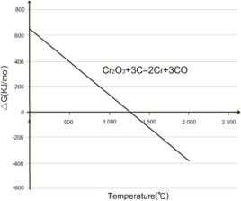
During the melting process, Cr is normally oxidized to form Cr2O3 in basic slag conditions and transferred into slag. The redox process of Cr can be analyzed by thermodynamic reactions as follows.
(Cr2O3) + 3[C] = 2[Cr] + 3{CO}(1)
The melting temperature can be determined by calculating the standard Gibbs free energy change with temperatures when chromium oxide reacts with carbon.
The results calculated by the custom application HSC-Chemistry 6.0 are shown in
Figure 1.
As shown in the
Figure 1, to prevent the oxidation of chromium, the melting temperature should be increased above the temperature at when the standard Gibbs free energy change △G is less than zero, and that temperature is usually above 1300°C.
The experiment was carried out to evaluate Cr yield when pure metal Cr was used as alloying agent in a medium frequency induction furnace.
The effect of melting temperature, chromium lump size and holding period on the degree of Cr adsorption on Cu was investigated in the experiment.
To study the influence of the parameters, the melting temperature was set at 1300°C and 1350°C, respectively, the chromium lump size was chosen to be in the range of 10-60 mm with respect to the floating period in the crucible and the retention period was set at 5 min with respect to the extreme value of Cr yield.
Figure 1. Variation of Gibbs free energy with temperature.
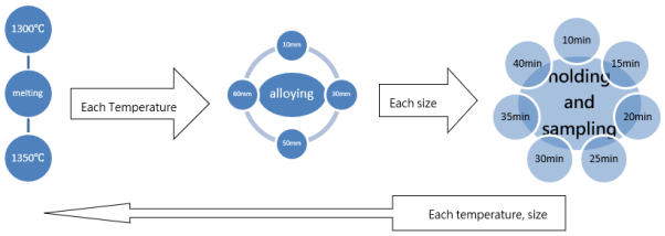
The experiment was carried out by charging chromium into the copper melt dissolved in a medium-frequency induction furnace and sampling and analyzing Cr yield.
The graphite crucible was put in a 500 kg medium frequency induction furnace, heated, charged with 60 kg of electric copper, melted and coated with 200 mm thickness of charcoal as a metal protector.
The graphite crucible is 200 mm in inner diameter, 300 mm in outer diameter and 600 mm in height.
First, when the melting temperature is 1300℃, 60g of Mg deoxidizer was added, the melt was stirred and the slag was removed. Then the sealed copper tube which contains 400 g of pure metal Cr lumps was prepared while varying the size of lump Cr by 10mm, 30mm, 50mm and 60mm. Next, the sealed copper tube was pushed into the bottom of crucible and the melt was stirred with a graphite rod 12 times per minute for alloying. Sampling was done after 10 minutes at first and then every 5 minutes in the middle part of the crucible. The same procedure was performed at 1350°C.
As shown in
Figure 2, the alloying melting test was performed eight times with two melting temperatures and four different lumps, and the sampling was done 56 times with seven different holding periods of eight different melts.
Figure 2. Experimental method.
The melting yield of Cr was analyzed by spectrophotometer UV-1801 and then calculated by the following formula.
where η - melting yield of Cr, %
M – Cr content in the feed, g
m – Cr content in molten metal, g
The composition of the melted alloy was analyzed with scanning electron microscope equipped with EDS analyzer (JSM-6610A).
3. Results and Discussion
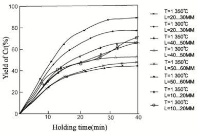
The test results of factors affecting on Cr yield are shown in
Figure 3.
Figure 3. Cr yield versus melting temperature, Cr lump size and holding period.
It can be seen that the yield is 80-90% when the melting temperature is 1300-1350°C with holding period of 30-40min and chromium lump size of 30 mm. However, when the chromium lump size decreases to 10 mm, the chromium yield decreases from 72 to 75%.
Cr reacts with the incoming oxygen diffused to the protective layer and the molten metal interface to form Cr2O3, and when dissolved in a graphite crucible, it reacts with carbon to form carbide Cr7C3.
The larger the lump size is, the slower the melting rate of Cr, the faster the chromium rise rate, the shorter the holding period, and therefore, there is a decrease in the Cr yield. The high specific surface area is due to the excessive agglomerate size, which increases the oxide film by oxygen adsorbed on the molten metal, so the dissolution rate is low and the dissolved Cr forms carbides by carbon adsorbed on the molten metal from the crucible and stirred rods, thus decreasing the Cr yield.
From the experimental result, a precise mathematical model for the overall effect of parameters was selected by sci-tech calculating program-MATLAB.
The parameters are temperature, holding period, and chromium lump size and the final objective function is the Cr yield. The general functions are as follows:
Y= b0+ b1·T + b2·L + b3·t + b4·T·L + b5·T·t + b6·L·t + b7·T·L·t + b8·T2+ b9·L2+ b10·t2(3)
Where Y- Cr yield, %
T- melting point, ℃
L- Cr lump size, mm
t- holding period, min
From the regression coefficient test (
Table 2) on the Student scale, the coefficients b
0, b
1, b
2, b
3, b
8, b
9 and b
10 were found to be significant.
Therefore, the regression equation is
Y=50.009+ 4.713T + 13.003t -11.22L + 7.207T2-15.133t2-12.425L2(4)
Table 2. Validation of regression coefficients.
Regression coefficient | Validation of regression coefficients on Student's scale |
Numerical value | | |
b0 | 50.009 | 20.8087 | 6.13 |
b1 | 4.713 | 28.4936 | 0.88 |
b2 | 13.003 | 28.4936 | 2.44 |
b3 | -11.22 | 28.4936 | -2.1 |
b4 | -1.035 | 39.0163 | -0.17 |
b5 | -1.095 | 39.0163 | -0.18 |
b6 | -3.135 | 39.0163 | -0.5 |
b7 | 1.215 | 39.0163 | 0.19 |
b8 | 7.207 | 75.51882 | 0.85 |
b9 | -15.133 | 75.51882 | -1.79 |
b10 | -12.425 | 75.51882 | -1.47 |
The consistency of the obtained equation (
4) was checked according to the Fisher criterion.
When the degree of freedom is f1 = 15-3-1 = 11, f2 = 3-1 = 2 and the significance level is 5%, F = 19.4, and the calculated Fisher criterion is F = 2.07. Therefore, the obtained regression equation is consistent with the process at the study area limit.
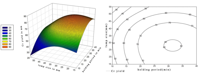
To see the influence of the selected factors on Cr yield, the influence surface and influence section were plotted (Figs. 4, 5, 6). Since three factors were changed in the experiment, only two factors were changed and the third one was fixed when each influence surface and influence section were made.
From
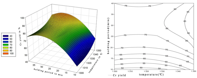
Figure 4, it can be seen that the chromium yield no longer increases after 35 min of holding when any size of chromium lump is used in the range of 10-60 mm. This is because, after 35 min, most of the chromium in the molten metal is absorbed and the remaining is oxidized and transferred into the oxide slag.
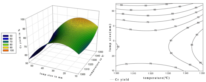
The maximum yield of chromium 90% is observed when the lump size of chromium is 30 mm and the holding period of the molten metal is 30-35 min. it can be seen that the chromium yield increases with increasing melting temperature from 1300 to 1350°C (
Figure 5) and the chromium yield reaches 80-90% at 30-35 min of holding. (
Figure 6).
As above, the maximum chromium yield 90% is reasonable when the melting temperature is 1350°C with the lump size of chromium is 25-30 mm and the holding period is 30-35 min.
In the melting of the Cu-Cr alloys by the commercial intermediate alloy, the percentage of the intermediate alloy in the charge is 22-25%, because of the low chromium content of the Cu-Cr intermediate alloy (generally not exceeding 6-7%).
However, in alloying with pure metal Cr, the preparation process of intermediate alloy is omitted and only small quantity of metallic Cr as the Cr content in alloy is needed.
Figure 4. Influence surface and influence cross section of Cr yield with lump size and holding period at temperature of 1300°C.
Figure 5. Influence surface and influence cross section of Cr yield with temperature and lump size at 30 min of holding period.
Figure 6. Influence surface and influence cross section of Cr yield with temperature and holding period at 35mm of lump size.
Table 3. Chemical composition of Cu-Cr alloy dissolved in air.
Alloy designation | Chemical element, Wt% |
Cu | Cr | Mg | Pb | Bi | P | Fe | O |
CuCr0.7 | 99.23 | 0.63 | 0.04 | 0.037 | 0.03 | 0.01 | 0.02 | 0.002 |
From
Table 3 it can be seen that the chemical composition of Cu-Cr alloy in the optimum solution conditions meets the technical specifications as a crystallographic copper tube material.
Depending on the lump Cr size, the melting rate and the floating period in the melt are different, and the dissolution and homogenous distribution should be completed within the floating process to increase the Cr yield.
The distribution is determined by the rate of diffusion, frequency and activation energy during crystallization, so that the distribution can be studied in the ingot state.
Under reasonable melting conditions, the CuCr0.7 alloy obtained by induction furnace melting and in-furnace crystallization takes the columnar structure (
Figure 7).
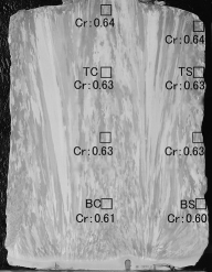
From
Figure 7, the distribution of Cr at the center and the surface of the top and bottom parts of the ingot is similar for the other parts, with a slight decrease in the amount of Cr at the bottom part. If the distribution is not equal, especially if upper Cr content(amount) is high, the floating period is shorter than the melting period, resulting in the low yield due to the slag floating.
Therefore, under the reasonable melting conditions, the yield is high because the distribution of Cr is uniform.
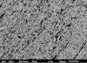
The microstructure of the castings obtained by melting and casting at 1300°C is shown in
Figure 8. As shown in the figure, the alloying of chromium without segregation is uniform.
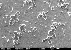
For the sake of detail, high magnified microstructure was shown in
Figure 9. As can be seen, chromium in the melt precipitates from the melt during cooling of the ingot, and the shape of the precipitated particles is mostly close to the spherical shape.
Figure 7. Microstructure and chemical composition on the longitudinal cross-section of inductively melted Cu-Cr alloys.
TC- top center part, TS- top surface part,
BC- bottom center part, BS- bottom surface part
Figure 8. SEM micrograph of alloy melted at 1300°C.
Figure 9. The shape of chromium particles in the molten alloy.
4. Conclusions
In this paper, the melting process of Cu-Cr alloys by a medium-frequency induction furnace is considered thermodynamically and the influence of melting process parameters on Cr yield is determined.
The maximum yield of Cr is 90% when the melting temperature is 1350℃ with a lump size of 30 mm and the holding period of 30-35 min.
Not only oxygen in the air but also nitrogen diffuses into the molten metal interface and reacts with the Cr to form Cr2N, and impurities such as sulfur in the feed react with the alloying element which decrease Cr yield.
In addition, metal oxides and oxide inclusions in the slag layer react each other to make the Cr loss more complicated and difficult to control during the melting of the alloy. With the expansion of the melt size, it is difficult to place deoxidizer or alloying metal into the bottom of the crucible, and the loss is high because of the floating on the melt, and the stirring process becomes very difficult.
At high temperatures, the water vapor in the air is dissolved into oxygen and hydrogen to mix with melt and as it has high amount of oxygen inclusion and gas absorption, the melting temperature shouldn’t be increased.
Since carbon from a graphite crucible reacts with Cr, it is preferable to use a zirconia or magnesia crucibles.
In Cu-Cr alloys, Mg increases the strength of alloy because the Mg particles are arranged along the grain boundaries, inhibiting the growth process and hindering the movement of dislocations, without forming compounds with Cr and without being dissolved.
Therefore, it is promising to investigate the Cu-Cr-Mg alloys in the future because Mg has the strongest deoxidation ability and can improve the physical and mechanical properties of the alloys.
Acknowledgments
It is also the result of collaborative research with State Academy of Sciences.
Funding
This work was partially supported by State Academy of Sciences.
Conflicts of Interest
The authors declare no conflicts of interest.
References
| [1] |
Filipe C, Gisele L. Effect of ECAP processing on distribution of second phase particles, hardness and electrical conductivity of Cu−0.81Cr−0.07Zr alloy Trans. Nonferrous Met. Soc. China. 32(2022) 217−232.
|
| [2] |
Fang H, Liu P. Effect of Ti addition on the microstructure and properties of Cu–Cr alloy. Mater. Sci. Technol. 37(2021) 672–681.
|
| [3] |
Wang Y, Qu J, Wang, X. Effects of Y addition on the microstructure, properties and softening resistance of Cu-Cr alloy. J. Alloys Compd. 902(2022) 163816.
|
| [4] |
Jun L, Cai Liu. Optimization of Mold Inverse Oscillation Control Parameters in Continuous Casting Process. Materials and Manufacturing Processes. 30 (2015) 563–568.
https://doi.org/10.1080/10426914.2015.1004696
|
| [5] |
Ma M, Xiao Z, Meng X. Effects of trace calcium and strontium on microstructure and properties of Cu-Cr alloys. J. Mater. Sci. Technol. 112(2022) 11–23.
|
| [6] |
Peng, H, Xie, W, Chen, H. Effect of micro-alloying element Ti on mechanical properties of Cu–Cr alloy. J. Alloys Compd. 85(22021) 157004–157013.
|
| [7] |
Li J, Ding H. Effect of Cr and Sn additions on microstructure, mechanical-electrical properties and softening resistance of Cu–Cr–Sn alloy. Mater. Sci. Eng. A. 802(2021) 140628–140637.
|
| [8] |
Sun Y, Peng L, Huang G. Effects of Mg addition on the microstructure and softening resistance of Cu–Cr alloys. Mater. Sci. Eng. A. 776 (2020) 139009–139019.
|
| [9] |
Yang X. H, Wang C. D, Yang L. Effects of Nb addition and different cooling methods on microstructures and properties of Cu-Cr Alloys. J. Mater. Eng. Perform. 29(2020) 5008–5017.
|
| [10] |
Yang Y, Kuang G, Li R. Optimizing the electrical and mechanical properties of Cu-Cr alloys by Hf microalloying. Metals. 12(2022) 485.
|
| [11] |
Huihui Xiong, Yingying Ma, Haihui Zhang. Design of Cu–Cr Alloys with High Strength and High Ductility Based on First-Principles. Calculations Metals 12(2022) 1406
|
| [12] |
WEI K X, WEI W, WANG F. Microstructure, mechanical properties and electrical conductivity of industrial Cu−0.5%Cr alloy processed by severe plastic deformation [J]. Materials Science and Engineering A, 528(2011) 1478−1484.
|
| [13] |
Dobatkin S. V, Gubicza J. High strength and good electrical conductivity in Cu–Cr alloys processed by severe plastic deformation [J]. Materials Letters 153 (2015) 5–9.
https://doi.org/10.1016/j.matlet.2015.03.144
|
| [14] |
J. Y. Cheng, F. X. Yu, B. Shen. Solute clusters and chemistry in a Cu–Cr–Zr–Mg alloy during the early stage of aging. Materials Letters 115 (2014) 201–204.
https://doi.org/10.1016/j.matlet.2013.10.055
|
| [15] |
Litian Zhang, Gang Yu. Surface nanocrystallization of Cu-Cr alloy by a high power density continuous laser beam. Materials Letters 237 (2019) 216–219.
https://doi.org/10.1016/j.matlet.2018.11.108
|
| [16] |
Z. Zhao, Z. Xiao, Z. Li, M. Ma, J. Dai, Effect of magnesium on microstructure and properties of Cu-Cr alloy, Journal of Alloys and Compounds 23 (2018) 155-161,
https://doi.org/10.1016/j.jallcom.2018.04.159
|
Cite This Article
-
APA Style
Om, C. J., Kim, H., Phyon, K. H., Pak, J. H., Ri, K. I. (2026). Research on Parameter Optimization for Cr Yield Under Atmospheric Induction Melting Process of Copper Mould Tube Material for Continuous Casting Machine. Science Discovery Physics, 1(1), 62-69. https://doi.org/10.11648/j.sdp.20260101.16
 Copy
|
Copy
|
 Download
ACS Style
Om, C. J.; Kim, H.; Phyon, K. H.; Pak, J. H.; Ri, K. I. Research on Parameter Optimization for Cr Yield Under Atmospheric Induction Melting Process of Copper Mould Tube Material for Continuous Casting Machine. Sci. Discov. Phys. 2026, 1(1), 62-69. doi: 10.11648/j.sdp.20260101.16
Copy
|
Download
AMA Style
Om CJ, Kim H, Phyon KH, Pak JH, Ri KI. Research on Parameter Optimization for Cr Yield Under Atmospheric Induction Melting Process of Copper Mould Tube Material for Continuous Casting Machine. Sci Discov Phys. 2026;1(1):62-69. doi: 10.11648/j.sdp.20260101.16
Copy
|
Download
-
@article{10.11648/j.sdp.20260101.16,
  author = {Chung Jin Om and Hyon Kim and Kum Hyok Phyon and Jin Hyang Pak and Kwang Il Ri},
  title = {Research on Parameter Optimization for Cr Yield Under Atmospheric Induction Melting Process of Copper Mould Tube Material for Continuous Casting Machine},
  journal = {Science Discovery Physics},
  volume = {1},
  number = {1},
  pages = {62-69},
  doi = {10.11648/j.sdp.20260101.16},
  url = {https://doi.org/10.11648/j.sdp.20260101.16},
  eprint = {https://article.sciencepublishinggroup.com/pdf/10.11648.j.sdp.20260101.16},
  abstract = {Cu-Cr alloys are widely used to extend the life of the copper mould tube for continuous casting machine (CCM) because of good wear and heat resistance. Current study is focused on the improvement of Cr yield under the atmospheric induction melting rather than vacuum melting of Cu-Cr alloys. The melting temperature was determined on the thermodynamic analysis of Cr redox process and metallic Cr rather than Cu-Cr intermediate alloy was used for alloying. The optimum conditions are melting temperature 1350℃, lump size 30 mm and holding period 30-35 min, witha chromium yield of 90%. At high temperatures, water vapor dissociates into oxygen and hydrogen, which increasesoxide inclusion and gas porosity. Since carbon from a graphite crucible reacts with Cr, it is preferable to use a zirconia or magnesia crucibles. It is considered positive to add magnesium to the copper-chromium alloy because magnesium is highly deoxidation-resistant and can improve the physical and mechanical properties of the alloy.},
 year = {2026}
}
Copy
|
Download
-
TY  - JOUR
T1  - Research on Parameter Optimization for Cr Yield Under Atmospheric Induction Melting Process of Copper Mould Tube Material for Continuous Casting Machine
AU  - Chung Jin Om
AU  - Hyon Kim
AU  - Kum Hyok Phyon
AU  - Jin Hyang Pak
AU  - Kwang Il Ri
Y1  - 2026/02/26
PY  - 2026
N1  - https://doi.org/10.11648/j.sdp.20260101.16
DO  - 10.11648/j.sdp.20260101.16
T2  - Science Discovery Physics
JF  - Science Discovery Physics
JO  - Science Discovery Physics
SP  - 62
EP  - 69
PB  - Science Publishing Group
UR  - https://doi.org/10.11648/j.sdp.20260101.16
AB  - Cu-Cr alloys are widely used to extend the life of the copper mould tube for continuous casting machine (CCM) because of good wear and heat resistance. Current study is focused on the improvement of Cr yield under the atmospheric induction melting rather than vacuum melting of Cu-Cr alloys. The melting temperature was determined on the thermodynamic analysis of Cr redox process and metallic Cr rather than Cu-Cr intermediate alloy was used for alloying. The optimum conditions are melting temperature 1350℃, lump size 30 mm and holding period 30-35 min, witha chromium yield of 90%. At high temperatures, water vapor dissociates into oxygen and hydrogen, which increasesoxide inclusion and gas porosity. Since carbon from a graphite crucible reacts with Cr, it is preferable to use a zirconia or magnesia crucibles. It is considered positive to add magnesium to the copper-chromium alloy because magnesium is highly deoxidation-resistant and can improve the physical and mechanical properties of the alloy.
VL  - 1
IS  - 1
ER  -
Copy
|
Download