5G construction is becoming increasingly important. This paper introduces the theoretical basis of multi-mode filter, and on the basis of theoretical calculation and analysis, a novel 5G cavity multi-mode resonator and filter is designed by using ads/HFSS simulation software. The electric field characteristic of resonator is analyzed, and the mutual coupling between modes is realized by the way of screw perturbation. The electric field distributions of the mode is changed by adding tuning screws, two coupled degenerate modes act as two coupled resonators, so that the numbers of resonator can be reduced while keeping the resonance loop unchanged. For example, the characteristics of 3N section filter can be realized in the physical space of a traditional n-section filter by using three modes of a resonator, thus greatly reducing the volume of the filter. The results show that in the pass-band (3.5 GHz ~ 3.6 GHz): return loss > 17.9 dB, standing wave ratio < 1.29, insertion loss < 0.31 dB, a transmission zero point is introduced at 4 GHz on the right side of the pass-band, which makes the right side out of band attenuation rapidly. The filter has the advantages of small insertion loss, small size and good rejection of out of band, which can be applied to 5G band wireless communication system for better reliability.
| Published in | International Journal of Wireless Communications and Mobile Computing (Volume 11, Issue 2) |
| DOI | 10.11648/j.wcmc.20241102.11 |
| Page(s) | 19-30 |
| Creative Commons |
This is an Open Access article, distributed under the terms of the Creative Commons Attribution 4.0 International License (http://creativecommons.org/licenses/by/4.0/), which permits unrestricted use, distribution and reproduction in any medium or format, provided the original work is properly cited. |
| Copyright |
Copyright © The Author(s), 2024. Published by Science Publishing Group |
5G Band, Cavity Filter, Multi-mode Filter, Hfss Simulation and Optimization, Standing-Wave Ratio, Insertion Loss
 (1)
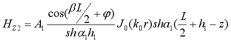
(1)  (2)
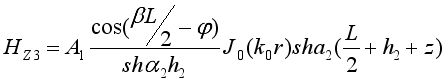
(2)  (3)
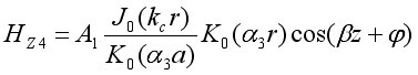
(3)  (4)
(4)  (5)
(5)  are constants, and at the same time:
  (6)
(6)  (7)
(7)  (8)
(8)  are known, then the components of other fields can be calculated as follows:
 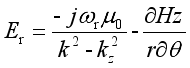 (8)
(8) 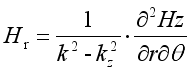 (9)
(9) 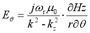 (10)
(10) 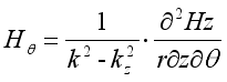 (11)
(11)  in the regions of 2 and 3, the propagation constants are zero for those TE modes independent of θ. Since the interface of the resonator is continuous, so (2) - (5) can be written as:
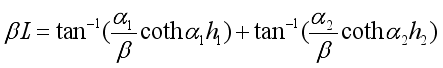
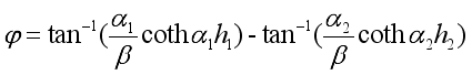
 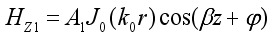 (12)
(12)  (13)
(13)  (14)
(14)  (15)
(15)  ,
,  is written as:
  (16)
(16)  (17)
(17)  (18)
(18)  (19)
(19)  (20)
(20)  (21)
(21)  (22)
(22)  (23)
(23)  and
and  are the first kind of Bessel functions in (10)-(21), and
  and
and  are the second kind of modified Bessel functions. On the boundary of
  , according to the boundary conditions of
  , it can be gotten that:
 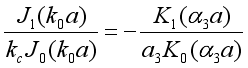 (24)
(24)  , according to the boundary conditions of
  , the following conclusions can be obtained:
 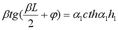 (25)
(25)  , according to the boundary conditions of
 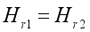 , the following conclusions can be obtained,
 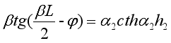 (26)
(26)  (27)
(27)  (28)
(28)  is the smallest root after arrange according to the size. Therefore, in modules independent of θ,
  is the lowest module, and which is the main module.
 The parameter of filter | |
|---|---|
Center frequency (f0) | 3550 MHz |
Absolute bandwidth (ABW) | 100 MHz |
Relative bandwidth (RBW) | 2.81% |
Standing wave ratio (VSWR) | 1.3 |
bandpass ripple (ε) | 0.6 dB |
Filter design size parameters | |
|---|---|
Unit | mm |
Rectangular metal external cavity | 26х26х28 |
Diameter/height of cylindrical dielectrics | 21/8.8 |
Diameter/height of supporting structure | 3/11 |
 value, that is, the position of the input and output ports is generally determined by the loaded
  value, and the relationship between
  and the coupling coefficient
  is
is  (29)
(29)  is the coupling coefficient between input port/output port and mode 2/mode 3. According to the electric field pattern of figure 6 to figure 7, a coupling probe is inserted at the bottom of the cylindrical medium, and the coupling probe is electrically coupled with the corresponding resonant mode. The coupling strength is directly proportional to the depth of the coupling probe penetrating into the bottom of the medium. After comprehensive consideration, the coupling probe length is 15.3 mm.
  (30)
(30)  is the resonant frequency of the first mode, and
  is the resonant frequency of the second mode.
 Paramaters | Initial value (mm) | Optimizated value (mm) |
|---|---|---|
The length of filter (a) | 28 | 26 |
The width of filter (b) | 28 | 26 |
The height of filter (c) | 28 | 28 |
The diameter/length of screw 1 | 1.6/9.8 | 2.0/9.5 |
The diameter/length of screw 2 | 1.5 | 1.5/0.8 |
5G | 5th Generation Mobile Communication Technology |
TE | Transverse Electric Wave |
TM | Transverse Magnetic Wave |
HEE | Hybrid Electric Electric |
HFSS | High Frequency Structure Simulator |
| [1] | ZOU De-hui, LAI Wan-chang, DAI Zhen-lin. Optimal Design of Microwave Band-pass Filter Based on ADS [J]. Electrical Measurement Instrumentation, 2007(06): 31-33. |
| [2] | JIANG Shuai. Researches on Microwave Multi-mode Dielectric Resonators and Filters [D]. Nanjing: Nanjing University of Aeronautics and Astronautics, 2017: 13-14. |
| [3] | Lin Wei-Guan. Microwave Filters Employing a Single Cavity Excited in More than One Mode. J. Appl. phys, 1951, 22(1): 989-1001. |
| [4] | H. Chang, K. A. Zaki. Evanescent-mode coupling of dual-mode rectangular waveguide filters. IEEE Trans. on MTT, 1991, 39(8): 1307-1312. |
| [5] | WANG Wen-xiang. Theory and Application of Microwave Engineering [M]. Cheng-du: Chengdu University of Electronic Science and Technology Press, 2006: 238-240. |
| [6] | GAN Ben-fu, WU Wan-chun. Structure and Design of Modern Microwave Filter [M]. Beijing: Science Press, 1973: 23-26. |
| [7] | Pozar D M. Microwave and RF Design of Wireless Systems [R]. New York: John Wiley & Sons. 2001. |
| [8] | QU Yongzhi, LI Dezhi, MA Yanshuang. Design of Finetuning Cavity Bandpass Filter Based on HFSS [J]. Radio Communications Technology, 2012, 38(3): 62-64. |
| [9] | PANG Hong, JIN Haiyan. A Compact Cross—Coupled SIR Bandpass Filter [J]. Piezoelectrics & Acoustooptics, 2010, 32(4): 618-621. |
| [10] | ZUO Yanran, LIU Wenjin, NAN Jingchang, GAO Mingming. Design of filter with notch bands based on multi-mode resonator [J]. Electronic Components and Materials, 2019, 38(2): 76-81. |
| [11] | LI Hui, WANG Litian, JI Lu, HE Ming, ZHAO Xinjie. Design of tri -band and quad-band filters based on multimode resonators [J]. Electronic Components and Materials, 2018, 37(12): 66-71. |
| [12] | CHU Qing-xin, LIN Jing-yu, WONG Shi-wai. Research on Cavity Multiple-Mode Filters and Multiplexers [J]. Journal of Microwaves, 2020, 36(1): 17-24. |
| [13] | XU Wei, LI Anyu, SHI Boya. A Novel Design Algorithm for Low Complexity Sparse FIR Notch Filters [J]. Journal of Electronics & Information Technology, 2019, 41(4): 939-944. |
| [14] | LIN J Y, WONG S W, WU Y M, et al. Three-way multiple-mode cavity filtering crossover for narrowband and broadband applications [J]. IEEE Transactions on Microwave Theory and Techniques, 2019, 67(3): 896-905. |
| [15] | Lin J Y, Wong S W, Wu Y M,et al.A New Concept and Approach for Integration of Three-State Cavity Diplexer Based on Triple-Mode Resonators [J]. IEEE Transactions on Microwave Theory and Techniques, 2018, PP (12): 5272-5279. |
| [16] | LIU Zhewei, WANG Jinzhao, JIANG Juan, GAN Lin, LEI Zelin, HU Xueqi, ZHANG Tianjin. Simulation design of cavity filters for 5G network base station [J]. Journal of Hubei University (Natural Science), 2019, 41(2): 163-167. |
| [17] | JIA Jianke, WANG Xinkuan, ZHENG Chunlai, YE Xiaodong. Study on resonance characteristics of multimode resonators based on material perturbation [J]. Electronic Components and Materials, 2019, 38(5): 84-88. |
| [18] | ZHU Qi-yu. Design and Simulation of Multiple-Mode Ceramic Filters [J]. Computer and Information Technology, 2017, 25(3): 8-10. |
| [19] | Hu H, Wu K L .A TM_{11} Dual-Mode Dielectric Resonator Filter With Planar Coupling Configuration [J]. IEEE Transactions on Microwave Theory & Techniques, 2013, 61(1): 131-138. |
| [20] | Hendry D R, Abbosh A M .Triple-Mode Ceramic Cavity Filters With Wide Spurious-Free Performance [J]. IEEE Transactions on Microwave Theory & Techniques, 2017, 65(10): 3780-3788. |
| [21] | D. R. Hendry and A. M. Abbosh. Analysis of compact triple-mode ceramic cavity filters using parallel-coupled resonators approach [J], IEEE Trans. Microwave Theory Technology, vol. 64, no. 8, pp. 2529–2537, Aug. 2016. |
| [22] | J.-F. Liang, K. A. Zaki, and A. E. Atia. Mixed modes dielectric resonator loaded cavity filters, IEEE MTT-S Int. Microw. Symp. Dig., May 1994, vol. 2. no. 9, pp. 731–734. |
| [23] | C. Wang, K. A. Zaki, and A. E. Atia. Dual mode combined dielectric and conductor loaded cavity filters, IEEE MTT-S Int. Microw. Symp. Dig., vol. 2. Jun. 1997, pp. 1103–1107. |
| [24] | Luo B, Zhan Z S, Fang B, et al. A Dual-Mode Dielectric Filter for 5G System [J]. Journal of Physics: Conference Series, 2021, 1992(4): 042071. |
APA Style
Luo, B., Li, Q. (2024). A Novel 5G Multi-mode Resonator and Filter with Symmetric Transmission Zeros. International Journal of Wireless Communications and Mobile Computing, 11(2), 19-30. https://doi.org/10.11648/j.wcmc.20241102.11
ACS Style
Luo, B.; Li, Q. A Novel 5G Multi-mode Resonator and Filter with Symmetric Transmission Zeros. Int. J. Wirel. Commun. Mobile Comput. 2024, 11(2), 19-30. doi: 10.11648/j.wcmc.20241102.11
AMA Style
Luo B, Li Q. A Novel 5G Multi-mode Resonator and Filter with Symmetric Transmission Zeros. Int J Wirel Commun Mobile Comput. 2024;11(2):19-30. doi: 10.11648/j.wcmc.20241102.11
@article{10.11648/j.wcmc.20241102.11,
  author = {Bing Luo and Qian-Qian Li},
  title = {A Novel 5G Multi-mode Resonator and Filter with Symmetric Transmission Zeros
},
  journal = {International Journal of Wireless Communications and Mobile Computing},
  volume = {11},
  number = {2},
  pages = {19-30},
  doi = {10.11648/j.wcmc.20241102.11},
  url = {https://doi.org/10.11648/j.wcmc.20241102.11},
  eprint = {https://article.sciencepublishinggroup.com/pdf/10.11648.j.wcmc.20241102.11},
  abstract = {5G construction is becoming increasingly important. This paper introduces the theoretical basis of multi-mode filter, and on the basis of theoretical calculation and analysis, a novel 5G cavity multi-mode resonator and filter is designed by using ads/HFSS simulation software. The electric field characteristic of resonator is analyzed, and the mutual coupling between modes is realized by the way of screw perturbation. The electric field distributions of the mode is changed by adding tuning screws, two coupled degenerate modes act as two coupled resonators, so that the numbers of resonator can be reduced while keeping the resonance loop unchanged. For example, the characteristics of 3N section filter can be realized in the physical space of a traditional n-section filter by using three modes of a resonator, thus greatly reducing the volume of the filter. The results show that in the pass-band (3.5 GHz ~ 3.6 GHz): return loss > 17.9 dB, standing wave ratio < 1.29, insertion loss < 0.31 dB, a transmission zero point is introduced at 4 GHz on the right side of the pass-band, which makes the right side out of band attenuation rapidly. The filter has the advantages of small insertion loss, small size and good rejection of out of band, which can be applied to 5G band wireless communication system for better reliability.
},
 year = {2024}
}
TY  - JOUR
T1  - A Novel 5G Multi-mode Resonator and Filter with Symmetric Transmission Zeros

AU  - Bing Luo
AU  - Qian-Qian Li
Y1  - 2024/09/06
PY  - 2024
N1  - https://doi.org/10.11648/j.wcmc.20241102.11
DO  - 10.11648/j.wcmc.20241102.11
T2  - International Journal of Wireless Communications and Mobile Computing
JF  - International Journal of Wireless Communications and Mobile Computing
JO  - International Journal of Wireless Communications and Mobile Computing
SP  - 19
EP  - 30
PB  - Science Publishing Group
SN  - 2330-1015
UR  - https://doi.org/10.11648/j.wcmc.20241102.11
AB  - 5G construction is becoming increasingly important. This paper introduces the theoretical basis of multi-mode filter, and on the basis of theoretical calculation and analysis, a novel 5G cavity multi-mode resonator and filter is designed by using ads/HFSS simulation software. The electric field characteristic of resonator is analyzed, and the mutual coupling between modes is realized by the way of screw perturbation. The electric field distributions of the mode is changed by adding tuning screws, two coupled degenerate modes act as two coupled resonators, so that the numbers of resonator can be reduced while keeping the resonance loop unchanged. For example, the characteristics of 3N section filter can be realized in the physical space of a traditional n-section filter by using three modes of a resonator, thus greatly reducing the volume of the filter. The results show that in the pass-band (3.5 GHz ~ 3.6 GHz): return loss > 17.9 dB, standing wave ratio < 1.29, insertion loss < 0.31 dB, a transmission zero point is introduced at 4 GHz on the right side of the pass-band, which makes the right side out of band attenuation rapidly. The filter has the advantages of small insertion loss, small size and good rejection of out of band, which can be applied to 5G band wireless communication system for better reliability.

VL  - 11
IS  - 2
ER  -
School of Electronics and Communications, Guangdong Mechanical & Electronical Polytechnic, Guangzhou, China
Biography: Bing Luo received the B. S. degree from Huazhong Normal University, Wuhan, China, in 2003, the Master degree from Beijing Information Science & Technology University, Beijing, China, in 2010, and is currently working toward the research and teaching of microwave device and wireless system in the Guangdong Mechanical and Electrical Polytechnic. He was a radio Engineer with the Research Department of Guangdong Fenghua Advanced Technology Holding CO., LTD from 2010 to 2012, where he was involved with numerical modeling of low-temperature co-fired ceramic (LTCC) layouts and passive integrated circuit components, automatic design of low noise amplifier for mobile systems. His research include non-planar filter, such as dielectric filter and micro-strip filter and compact multimode filter design and application for next-generation wireless base-station systems, analytical computer-aided tuning (CAT) techniques, computational EM algorithms for modeling of waveguide structures, and frequency- and time-domain numerical modeling and analysis of multilayered high-speed RF circuits.
Research Fields: filter, radio filter, antenna, balun, LNA

School of Electronics and Communications, Guangdong Mechanical & Electronical Polytechnic, Guangzhou, China
Biography: Qian-Qian Li received the B. S. degree in communication engineering from the Hunan University of Science and Technology, Xiangtan, China, in 2015, the M. S. degree in information and communication engineering from Central South University, Changsha, China, in 2018, and the Ph.D. degree in the South China University of Technology, Guangzhou, China, in 2021. She is current working toward the research and teaching of intelligent optimization algorithms, array antennas, and MIMO antennas in the Guangdong Mechanical and Electrical Polytechnic.

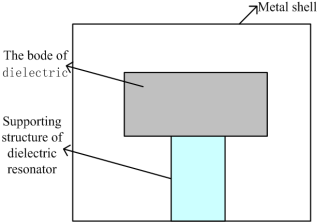
Figure 1. The structure of dielectric resonator.
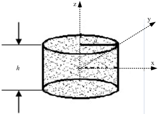
Figure 2. Isolated dielectric resonator.
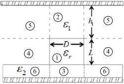
Figure 3. The diagram of dielectric resonator.
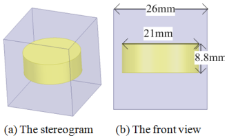
Figure 4. The mode of dielectric resonator.
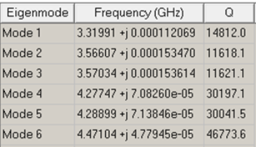
Figure 5. The results of eigen mode simulation.
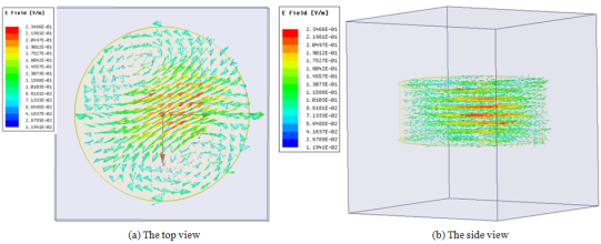
Figure 6. The electric field pattern of HEE11 degenerate two mode along the radial clockwise 45° polarization mode.
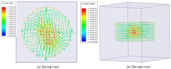
Figure 7. Electric field diagram of HEE11 degenerate two mode along radial counter clockwise 45° polarization mode.
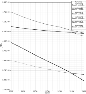
Figure 8. Relationship between resonant frequency and diameter D of eight modes in dielectric resonator.
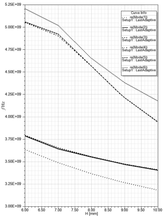
Figure 9. Relationship between resonant frequency and height H of eight modes in dielectric resonator.
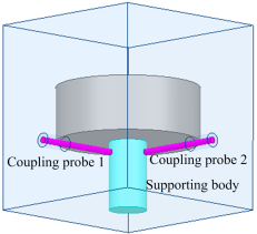
Figure 10. Coupling probe extending into the bottom of resonator.
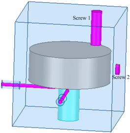
Figure 11. Location of perturbation coupling screw.
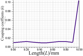
Figure 12. Relationship between the length of screw 1 and coupling coefficient.
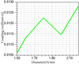
Figure 13. Relationship between the diameter of screw 1 and coupling coefficient.

Figure 14. Influence of coupling screw length on filter parameter S11.
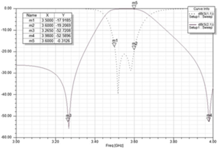
Figure 15. return loss and insertion loss of dielectric filter.
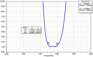
Figure 16. VSWR of dielectric filter.
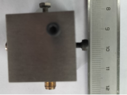
Figure 17. Fabricated photograph of physical filter.
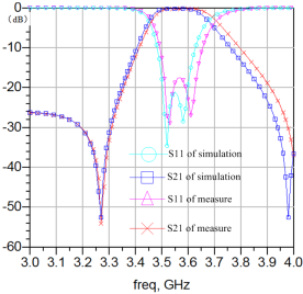
Figure 18. Comparison between simulated and measured s parameters.
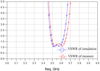
Figure 19. Comparison between simulated and measured VSWR.
Information