Research Article | | Peer-Reviewed

Design and Realisation of a Motorized Beans Shelling Machine

Received: 15 April 2026     Accepted: 3 May 2026     Published: 28 July 2026
Views:       Downloads:
Abstract

Common beans (Phaseolus vulgaris L.) are an essential staple crop widely grown across many developing nations. Recognizing the significant value and potential of this crop has led to the push for creating a mechanized bean shelling system as part of modern agricultural planning. This study focused on design and realisation of beans shelling machine. The machine was designed and realisation was achieved using appropriate engineering materials selected for various parts of the machine. This machine incorporated an air chamber system which was used in air production for waste disposal. Peeled beans was collected via a collecting vessel. Pulleys were used as speed reducers to transmit power and movement in order to enhance efficiency of the machine and the preservation of the good quality product. The machine performed well when it is motorised with a 2HP motor 1400rpm and a turning speed of 950rpm and average torque of 4.944Nm. Pulley groove selected at 206mm. we obtained for 92.7% beans peeling efficiency with a 630.32 kg/h of beans shelled.

Published in American Journal of Mechanical and Industrial Engineering (Volume 11, Issue 3)
DOI 10.11648/j.ajmie.20261103.11
Page(s) 38-44
Creative Commons

This is an Open Access article, distributed under the terms of the Creative Commons Attribution 4.0 International License (http://creativecommons.org/licenses/by/4.0/), which permits unrestricted use, distribution and reproduction in any medium or format, provided the original work is properly cited.

Copyright

Copyright © The Author(s), 2026. Published by Science Publishing Group

Keywords

Design, Realisation, Beans, Shelling Machine

1. Introduction
Common beans (Phaseolus vulgaris L.) are a major food and income source in many developing regions. Their high nutritional value—consisting of proteins, minerals, vitamins, and dietary fibre—makes them a key component of diets in sub-Saharan Africa. In Cameroon, bean cultivation has expanded considerably, positioning the country as the seventh-largest producer in the region. National production rose from approximately 365,295 metric tons in 2017 to 373,624 metric tons in 2021, driven largely by population growth and increasing urban demand. However, this rise in production has not translated into lower market prices, largely due to persistent constraints in the production and post-harvest chain. These challenges include limited access to improved seed varieties, outdated farming tools, declining soil fertility, inadequate pest control, and substantial post-harvest losses. Manual shelling remains one of the most labor-intensive bottlenecks, contributing significantly to inefficiencies in the value chain.
The introduction of agricultural machinery has been widely recognized as a means to improve efficiency and product quality. Olaoye highlighted that although mechanical shelling technologies may involve high initial investment, they reduce labor intensity, maintain kernel quality, and minimize losses compared with traditional methods. This has encouraged several research efforts aimed at developing cost-effective shelling machines, particularly using locally available materials.
Unuigbe et al. designed and constructed a bean sheller using local materials, supported by detailed component design and fabrication drawings. Their machine achieved a shelling efficiency of 81.3% with a processing capacity of 100 kg/h, demonstrating the feasibility of low-cost mechanical solutions. Ilori et al. investigated ergonomic factors in hand-operated shellers, identifying that operator characteristics such as age, weight, and arm length significantly influence shelling efficiency, an important consideration for manually powered devices.
Other studies have focused on optimizing machine design for higher performance. Ashwin and Shaik developed a hand-operated cylinder–concave sheller that reached a shelling efficiency of 99.56% at 12% moisture content and 130 kg/h feed rate, with minimal unshelled grains and acceptable grain damage. Engineers at the USDA designed an experimental gentle-handling sheller, which performed well at 15% moisture content but suffered from issues related to belt durability, low throughput, and reduced efficiency at higher moisture levels. Fox proposed a rubber-roller sheller based on rolling and squeezing principles; however, it faced feeding limitations and did not perform satisfactorily on unhusked pods. Research on similar post-harvest processes provides useful insight into efficiency gains from mechanization. Karthickumar et al. developed a continuous tamarind deseeding machine with a throughput of 75 kg/h and a maximum efficiency of 89.15%, reducing both cost and processing time relative to manual methods. Similarly, Hiregoudar and Udhayakumar found that mechanical deseeding significantly increases output compared with traditional techniques, although at the cost of higher mechanical damage.
Additional studies by Aluko , Babatunde et al. , and Uadia and Ogbu focused on the design, fabrication, and evaluation of bean shelling machines with the aim of improving shelling efficiency, reducing processing time, and minimizing losses. These works collectively emphasize methodologies for machine design and the potential benefits of mechanization in bean processing. A review of the literature shows that while many prototypes have been developed, several challenges persist: Low shelling efficiency in early designs, Limited processing capacity, restricting commercial use, High levels of grain damage, often linked to bean size variability, Mechanical limitations, such as poor feeding systems or fragile components, Lack of standardization, with many machines remaining at prototype stage.
Given these limitations, there is a clear need for a more efficient, robust, and commercially viable bean shelling machine adapted to local conditions. The current study responds to this need by designing and developing a locally fabricated sheller capable of improving throughput, reducing mechanical damage, and supporting wider adoption of mechanized post-harvest technologies.
2. Materials and Method
2.1. Design Consideration
The design and development of a bean shelling machine must consider several important factors, including product quality, material selection, and process efficiency. Product quality is evaluated based on the preservation of the beans’ physical and chemical properties. The construction materials should be resistant to corrosion, wear, and tear, while also being strong, readily available, and affordable. Other key considerations include the machine’s structural stability, ensuring it remains rigid during operation, and its ability to sort, meaning the separation of shelled beans into uniform aggregates within the shelling chamber. Affordability is also crucial, enabling farmers to compare the machine’s investment and maintenance costs with those of imported alternatives.
2.2. Conceptual Design
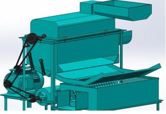
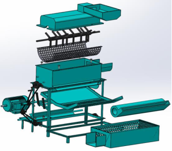
AutoCAD software was used to design components and to assembly them for the geometrical model of the machine. It was also used to simulate the rigidity of the frame in other to choose the suitable materials that could withstand the loads and preserve the stability. Figures 1 and 2 show respectively the exploded and isomeric views of the machine designed.
Figure 1. Exploded view of beans shelling machine.
Figure 2. Isometric view of motorized beans Sheller.
2.3. Design Analysis and Calculations
The design of various component parts of shelling machine is governed by physical, mechanical and engineering properties of beans. Others are the mechanism of rotating shaft over the concave at a specific clearance for the downward movement of the shelled grains. We are going to present the design analysis and calculations for major component parts.
2.3.1. Frame
The two primary factors considered in selecting the frame material were weight and strength, as the frame would be subjected to compressive forces and torque. In this study, a hollow square steel tube (S235JR, 16 mm × 5 mm) was used to provide the necessary rigidity. The frame components were fabricated through cutting with an angle grinder, and the assembly was completed using the MIG/MAG welding process.
2.3.2. Hopper
The hopper is designed to be fed in a horizontal position only. The material used for the construction is carbon steel S235 JR 2000x 1000 sheet metal, which is readily available in the market and relatively affordable.
2.3.3. Beans Inlet Vessel
It was done by carbon steel S235 JR 2000x 1000 Cutting via a shearing machine and Bending via an angle bending machine with the dimensions of 470mm x 285.69mm.
2.3.4. Sieve Chamber Connected to Mechanism
It has the dimensions of 850mm x 360mm realized with carbon steel by cutting using the shearing machine.
2.3.5. Blower
It is the composition of the fan system with fan blades of 500mm x100mm enclosed in the shaft realized by Cutting/Cleaning and the Air chamber of 767mm x 200mm, Radius 80mm realized with cutting, Rolling and Welding process.
2.3.6. Design of Shaft
It is a cylindrical solid rod for transmitting motion through a set of load carried on it. The design is based on fluctuating torque, bending moment and shearing force.
Determination of Maximum Bending Moment 𝑀𝑏
The maximum bending moment is given by equation (1)
Mb=MBV2-MBH2(1)
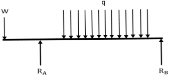
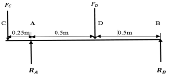
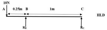
Where 𝑀𝐵𝑉 is the vertical bending moment (Nm).and 𝑀𝐵𝐻 the horizontal bending moment (Nm). Figure 3 bellow presents the different loads acting on the shaft. W represents the centrifugal force of the pulley, q is the uniformly distributed loads in housing chamber due to weight of beans and RA, RB are reactions of the bearings. Figure 4 presents forces acting on the shaft to be calculated.
Figure 3. Representation of loads acting on the shaft.
Figure 4. Representation of forces to be calculated.
Calculations:
Weight of pulley W= 1kg = 1kg x 10 = 10N
Weight of beans M= 𝜌𝑉 = 𝜋𝐷2𝐿𝜌 =3.14 x 0.32 𝑥 1 𝑥 24= 6.7kg = 6.7kg x 10 = 67N
Taking moment about RA: -10N x 0.25m -RB x 1m + 67N x 0.5m = 0 -2.5- RB+ 33.5=0
RB= 31N
RA=46N
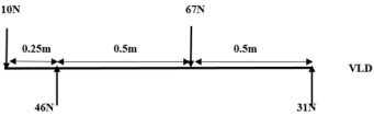
Figure 5 presents the vertical loading diagram
Figure 5. Vertical loading diagram.
At C, MBV =0
At A, when x = 0.25 m MBV = 10 x 0.25 = 2.5Nm
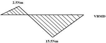
At D, when x = 0.75 m MBV = (10 x 0.75) – (46 x 0.5) MBV = - 15.5Nm
Figure 6 presents vertical bending moment diagram.
Figure 6. Vertical bending moment diagram.
Calculations of horizontal bending moment
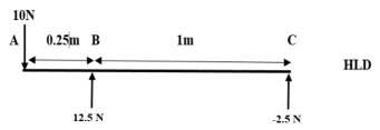
Figure 7 presents the Horizontal loading.
Figure 7. Horizontal loading.
From Figure 7, taking moment about RB:
0 = 10N x 0.25m + RCx 1m; 0 = 2.5 + RCRC=− 2.5N
RB+ RC= 10N, RB= 12.5 N
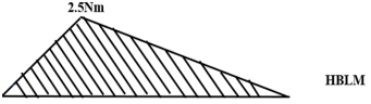
Figures 8 and 9 present horizontal loading force diagram and horizontal bending moment diagram respectively.
Figure 8. Horizontal loading force diagram.
At A, MBH =0
At B, when x = 0.23 m MBH = 10 x 0.25 = 2.5 Nm
At C, when x = 1.25 m MBH = (10 x 1.25) – (12.5 x 1) MBH = 0 Nm
Figure 9. Horizontal bending moment diagram.
Therefore the maximum bending moment is:
M𝑏=15.52-2.52=15.70 Nm
Determination of Torsional Moment, Mt
The torsional moment, Mt is given by
Mt=FDx r
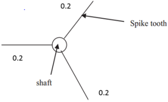
where r is the length of the sprike tooth linked on the shaft by welding process and constitute shelling mechanism. The diagram is presented on Figure 10 bellow.
Figure 10. Shelling mechanism.
Mt=6.7 x 0.2= 1,34 N.m
Determination of shaft diameter
For proper designing there is need to determine the shaft diameter, equation (2) was adopted:
d3=16πδsKbMb2+KtMt212(2)
where d is diameter of shaft (mm), Kb are bending moment fatigue and shock, Kt are fatigue and combined factor for torsional moment, Mb are resultant bending moment (Nm), Mt are resultant torsional moment (Nm), δsy are allowable bending stress (MN m-2).
Assumptions:
δs = 47 x 106N/m Kt=Kb=1.5
d3=1647 x 106 π1.5x15.7 2+ 1.5x1.34212
d=0.01644m
We should choice a diameter of 20mm.
2.3.7. Materials Selection
Power requirement of motorized beans Shelling. The Power P (W) requirement was calculated based on the motor and belt efficiency of 70% and 75% respectively using equation (3).
P=P'motor efficiency x belt efficiency x safety factor(3)
Where P’ is the theorical power (W)
P’= F × V
Where F is force of shelling (N), V are velocity (m/s).
V =𝜋DN
According to , the shelling speed that will give very low mechanical damage, but high threshing output is within the range of 950 revolutions per minute.
Let’s us take N=950 rpm and safety factor equal to 2
P’= 15.5 × 3.14 x 0.4 x 950/60 =368W
P=36870% x 75% ×2
P= 1400W
Then the motor power should be around 2HP since 1HP=737W
Determination of the diameter of the driven pulley
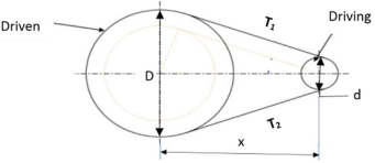
To calculate the diameter D of the driven pulley we use the Figure 11 representing the pulleys-belt system. The equation (5) presents the relationship between the diameters and rpm of the two pulleys.
Figure 11. pulleys-belt system.
N1d = N2D (5)
N1speed of driver=1400rpm and N2speed of driven
D diameter ofdriven and d diameter of driver=140mm
D=N1dN2=1400X140850= 206
D= 206 mm
2.3.8. V-belt Selection
Length of belt
For a motor rating of 0.7W, the suitable choice is class A with a pitch length of 1.06mm according to IS: 2494 – 1974 standard. Top width of 13mm. we choice a standard length of 925 mm.
Centre Distance of Belt
The length of the belt is given by the equation (6);
L = 2x + (π/2)(D + d) + (D – d)2/(4x)(6)
Where; L = length of belt, D and d are the diameter of the driven and driving pulleys respectively,
x = centre-to-centre distance between the driving and driven pulleys.
925 = 2x + (π/2)(206+ 130) + (206–130)2/(4x)
x = 200mm
The power transmitted by belt is given by equation (7)
P = (T1 – T2)V(7)
V = (πDN)/60. Also,
T1/T2= exp(μθ cosec β),
where:
β= groove semi-angle 2β = 34;
θ= angle of lap;
α= angle of contact at the smaller pulley;
μ= coefficient of friction.
The coefficient of friction for rubber belt on cast iron or steel operating on dry surface is μ = 0.3. The angle of lap for open V-belt drive is given as:
x = distance between pulleys;
d = diameter of smaller pulley;
D = diameter of bigger pulley.
θ = (180 – 18.4) x π/180=2.81rad
P = πDN (T1– T2)/60 T1– T2=60X14003.14X0.130x1500=137
T1/T2= exp(0.3x2.81x cosec17) =2.2
 T2+137 T2=2.2
T2=114N
T1=250N
3. Results and Discussions
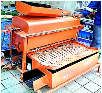
Figure 12 is the beans shelling machine realised.
Figure 12. Beans shelling machine realised.
3.1. Working Principle of the Beans Shelling Machine
Untreated beans is fed into the hopper then channels the beans to the hopper top cover through the shield box. The shield box prevents beans from pouring and therefore channels the beans to the rotor mechanism. The mechanism is made up of a shaft with square tubes welded on the surface of the shaft. This is the main part of the machine because this causes the force used in beating the beans. It is enclosed to the bottom hopper and a sieve vessel. The sieve vessel contains holes drilled at 10mm which serves as channel for the peeled beans to pass through. The bottom hopper contains an outlet where the peeled beans pass through. The peeled beans then fall on the sieve plate. The sieve plate is connected to the hopper bottom cover via connecting rod. The connecting rod is linked to the hopper bottom cover and the sieve plate via drilled holes of 10mm screwed properly to ensure stability. The stability of the plate is reinforced by sieve carrier below the sieve plate. As the peeled beans falls on the sieve plate, air issupplied by the air chamber caused by rotation of fan blades. Air produced blows off dirt particles found in the sieve plate and dust particles found the beans collector vessel. Fine beans are then channelled to the receiving vessel.
3.2. Performance Test
The shelling machine was subjected to test and it was discovered to shelling beans very effectively having negligible losses and breakages. The estimated capacity of the machine is about was 630.32 kg/h. The efficiency of the machine was calculated from the equation (8) below to be equal to 92.7%.
Efficiency= ((𝑊1−𝑊2)/𝑊1)100 (8)
Where 𝑊1 is the weight of unshelling beans
W2 is the weight of beans shelling beans.
4. Conclusions
The beans shelling machine fabricated shall peel harvested beans from our farms rapidly without any effect to the economy. This machine uses both man power and electricity power supply of 220volts at its standards. Skilled personnel are not needed in operating this machine because its parts are made easy to be operated upon by all farmers. Equally, its parts are made easy Such that when damaged or wear, it can be maintain. Moreover, it is cost efficient and its value is absolutely enjoyable. No radioactive gas emission or associated to its functionality. Uses the beating system which can easily be understood by all farmers since it is an improvement from hand beating.
Abbreviations

HP

Horse Power

MIG/MAG

Metal Inert Gaz/ Metal Active Gaz

𝑀𝐵𝑉

Vertical Bending Moment

𝑀𝐵H

Horizontal Bending Moment

Author Contributions
Noutegomo Boris: Conceptualization, Data curation, Formal Analysis, Investigation, Methodology, Supervision, Writing – review & editing
Neh Sandra Fongeh: Formal Analysis, Software, Validation, Writing – original draft
Beching Roland Oru: Conceptualization, Methodology, Writing – review & editing
Data Availability Statement
The data that support the findings of this study are openly available.
Conflicts of Interest
The authors declared that there is no conflict of interest.
References
[1] J. O. Olaoye, Development of a treadle operated abrasive-cylinder for threshing cowpea, International Journal of Engineering Science and Technology, 2011, 3(12): 8548-8557.
[2] A. Unuigbe, H. Unuigbe, E. Aigboje, P. Ugboya, Design and Development of Beans (Phaseolus Vulgaris) Shelling Machine, Innovative Systems Design and Engineering, (2017), Vol. 8, No. 1.
[3] T. A. Ilori, A. Raji, O. Kilanko, Modelling some ergonomic parameters with machine parameter using hand powered Corn Sheller, International Journal for Innovative Research in Science & Technology, 1981, Vol. 01, pp 2349-6010.
[4] B. Ashwin, & H. B. Shaik, Design, development and performance evaluation of a hand operated Maize Sheller, International Journal for Innovative Research in Science & Technology, 1980, Vol. 1, pp 2349-6010.
[5] USDA. Hugs and squeezes, 1967, Agr. Res, Vol. 16, pp 17.
[6] R. E. Fox, Development of a compression type bean threshing cylinder, Unpublished M.S. thesis. Library, Iowa State University, Ames, Iowa, 1969.
[7] P. Karthickumar, N. S. Karpoora, Pandian, P. Rajkumar, A. Surendrakumar, M. Balakrishnan, Development and Evaluation of a Continuous Type Tamarind Deseeder, Institute of Agricultural Engineering Scientific Journal Agricultural Engineering, 2015, Vol. 2, pp 49 – 59.
[8] S. Hiregoudar R. and Udhayakumar, Tamarind defibrating in traditional and mechanical methods A comparative study, Journal of Extension and Research, 2002, Vol. 4, Number 1 and 2, pp 125-129.
[9] G.M. Aluko, Design and Development of a Bean Shelling Machine black-mug-beans pealing machine-433html, 2003.
[10] Babatunde, Design, Fabrication and Performance Evaluation of a Bean Sheller, food journal, 2012.
[11] A.B. Fashina, H. Abdulahi, Performance evaluation of a locally developed direct-power-take off driven maize thresher, Journal of Agricultural Technology, 1994, vol. 2, no. 1, p. 1-5.
Cite This Article
  • APA Style

    Boris, N., Fongeh, N. S., Oru, B. R. (2026). Design and Realisation of a Motorized Beans Shelling Machine. American Journal of Mechanical and Industrial Engineering, 11(3), 38-44. https://doi.org/10.11648/j.ajmie.20261103.11

    Copy | Download

    ACS Style

    Boris, N.; Fongeh, N. S.; Oru, B. R. Design and Realisation of a Motorized Beans Shelling Machine. Am. J. Mech. Ind. Eng. 2026, 11(3), 38-44. doi: 10.11648/j.ajmie.20261103.11

    Copy | Download

    AMA Style

    Boris N, Fongeh NS, Oru BR. Design and Realisation of a Motorized Beans Shelling Machine. Am J Mech Ind Eng. 2026;11(3):38-44. doi: 10.11648/j.ajmie.20261103.11

    Copy | Download

  • @article{10.11648/j.ajmie.20261103.11,
      author = {Noutegomo Boris and Neh Sandra Fongeh and Beching Roland Oru},
      title = {Design and Realisation of a Motorized Beans Shelling Machine},
      journal = {American Journal of Mechanical and Industrial Engineering},
      volume = {11},
      number = {3},
      pages = {38-44},
      doi = {10.11648/j.ajmie.20261103.11},
      url = {https://doi.org/10.11648/j.ajmie.20261103.11},
      eprint = {https://article.sciencepublishinggroup.com/pdf/10.11648.j.ajmie.20261103.11},
      abstract = {Common beans (Phaseolus vulgaris L.) are an essential staple crop widely grown across many developing nations. Recognizing the significant value and potential of this crop has led to the push for creating a mechanized bean shelling system as part of modern agricultural planning. This study focused on design and realisation of beans shelling machine. The machine was designed and realisation was achieved using appropriate engineering materials selected for various parts of the machine. This machine incorporated an air chamber system which was used in air production for waste disposal. Peeled beans was collected via a collecting vessel. Pulleys were used as speed reducers to transmit power and movement in order to enhance efficiency of the machine and the preservation of the good quality product. The machine performed well when it is motorised with a 2HP motor 1400rpm and a turning speed of 950rpm and average torque of 4.944Nm. Pulley groove selected at 206mm. we obtained for 92.7% beans peeling efficiency with a 630.32 kg/h of beans shelled.},
     year = {2026}
    }
    

    Copy | Download

  • TY  - JOUR
    T1  - Design and Realisation of a Motorized Beans Shelling Machine
    AU  - Noutegomo Boris
    AU  - Neh Sandra Fongeh
    AU  - Beching Roland Oru
    Y1  - 2026/07/28
    PY  - 2026
    N1  - https://doi.org/10.11648/j.ajmie.20261103.11
    DO  - 10.11648/j.ajmie.20261103.11
    T2  - American Journal of Mechanical and Industrial Engineering
    JF  - American Journal of Mechanical and Industrial Engineering
    JO  - American Journal of Mechanical and Industrial Engineering
    SP  - 38
    EP  - 44
    PB  - Science Publishing Group
    SN  - 2575-6060
    UR  - https://doi.org/10.11648/j.ajmie.20261103.11
    AB  - Common beans (Phaseolus vulgaris L.) are an essential staple crop widely grown across many developing nations. Recognizing the significant value and potential of this crop has led to the push for creating a mechanized bean shelling system as part of modern agricultural planning. This study focused on design and realisation of beans shelling machine. The machine was designed and realisation was achieved using appropriate engineering materials selected for various parts of the machine. This machine incorporated an air chamber system which was used in air production for waste disposal. Peeled beans was collected via a collecting vessel. Pulleys were used as speed reducers to transmit power and movement in order to enhance efficiency of the machine and the preservation of the good quality product. The machine performed well when it is motorised with a 2HP motor 1400rpm and a turning speed of 950rpm and average torque of 4.944Nm. Pulley groove selected at 206mm. we obtained for 92.7% beans peeling efficiency with a 630.32 kg/h of beans shelled.
    VL  - 11
    IS  - 3
    ER  - 

    Copy | Download

Author Information
  • Department of Mechanical and Industrial Engineering, Universality of Bamenda, Bambili, Cameroon
  • Department of Mechanical and Industrial Engineering, Universality of Bamenda, Bambili, Cameroon

  • Department of Mechanical and Industrial Engineering, Universality of Bamenda, Bambili, Cameroon