Abstract
The corrosion of conventional steel reinforcement remains a major durability concern in reinforced concrete members exposed to chlorides, carbonation, moisture and industrial chemicals, because progressive section loss and bond deterioration can reduce stiffness, serviceability and structural reliability. Carbon fiber-reinforced polymer (CFRP) bars provide high tensile strength, low density and excellent resistance to electrochemical corrosion; however, their linear-elastic response up to rupture and comparatively different bond and stiffness characteristics can produce brittle failure and limited warning when they are used as the sole longitudinal reinforcement. The present study experimentally investigates partial replacement of steel tensile reinforcement by CFRP bars in reinforced concrete beams, with the objective of identifying a hybrid reinforcement ratio that improves strength and durability while retaining an acceptable level of deformation capacity. Five M30 concrete beam specimens, each measuring 700 mm x 100 mm x 100 mm, were prepared with constant geometry, concrete grade, loading arrangement and total number of bottom tensile bars. The specimens B-S100, B-C25, B-C50, B-C75 and B-C100 represented 0%, 25%, 50%, 75% and 100% CFRP replacement, respectively. The experimental programme comprised M30 mix proportioning, reinforcement cage fabrication, tensile characterization of steel and CFRP bars, 28-day curing and four-point flexural testing in accordance with the general principles of relevant concrete and composite testing standards. During testing, first-crack load, ultimate load, mid-span deflection, ductility index, energy absorption, stiffness, crack development and expected failure characteristics were evaluated. The adopted M30 mix contained 394 kg/m3 cement, 197 L/m3 water, 787 kg/m3 fine aggregate and 1082 kg/m3 coarse aggregate at a water-cement ratio of 0.50. Material testing indicated a peak load of 39.30 kN at 4.70 mm displacement for the steel sample and 45.95 kN at 6.80 mm for the CFRP sample, confirming the higher tensile resistance of CFRP while emphasizing the need to preserve the yielding contribution of steel in hybrid members. The beam results showed a systematic increase in first-crack load from 4.2 kN for B-S100 to 5.2 kN for B-C100 and an increase in ultimate load from 18.50 kN to 31.00 kN. Conversely, ultimate deflection reduced from 10.5 mm to 6.2 mm and the ductility index decreased from 3.50 to 1.20 as CFRP replacement increased. Among the hybrid configurations, B-C50 developed an ultimate load of 24.80 kN, an ultimate deflection of 9.00 mm, a ductility index of 2.70 and the maximum energy absorption of 133 N-m. It also provided the most favorable combined response in terms of strength enhancement, crack control, deformation reserve and energy dissipation. The findings demonstrate that full CFRP replacement maximizes flexural capacity but substantially reduces ductile warning, whereas moderate hybridization permits the complementary use of steel yielding and CFRP tensile resistance, as reported in previous hybrid beam research. Accordingly, 50% CFRP replacement is recommended as the optimum configuration for the present small-scale beam system. This recommendation is limited to the adopted geometry, material properties and test conditions, and should be validated through replicated tests, larger specimens, long-term durability exposure and numerical modelling before application to full-scale structural design.
|
Published in
|
Advances in Materials (Volume 15, Issue 3)
|
|
DOI
|
10.11648/j.am.20261503.14
|
|
Page(s)
|
110-131 |
|
Creative Commons
|

This is an Open Access article, distributed under the terms of the Creative Commons Attribution 4.0 International License (http://creativecommons.org/licenses/by/4.0/), which permits unrestricted use, distribution and reproduction in any medium or format, provided the original work is properly cited.
|
|
Copyright
|
Copyright © The Author(s), 2026. Published by Science Publishing Group
|
Keywords
CFRP Bars, Steel-CFRP Hybrid Reinforcement, Reinforced Concrete Beam, M30 Concrete, Flexural Behaviour,
Four-point Bending, Ductility, Energy Absorption
1. Introduction
Reinforced concrete beams contain embedded steel reinforcement to resist tensile forces. Steel is widely used because of its high elastic modulus, yielding behaviour, strong bond with concrete and post-cracking deformation capacity. These properties provide strength, stiffness and ductility. However, exposure to chlorides, carbonation, moisture and aggressive chemicals can initiate corrosion of embedded steel. The resulting corrosion products occupy a greater volume than the original reinforcement and generate radial pressure, causing longitudinal cracking, cover spalling, bond deterioration and progressive loss of steel area. Consequently, maintenance and repair costs increase, while the service life of bridge decks, marine structures and other exposed members may decrease
| [1] | B. WEI, X. HE, M. Zhou, H. Wang, and J. He, "Experimental study on flexural behaviors of FRP and steel bars hybrid reinforced concrete beams," Case Studies in Construction Materials, vol. 20, Art. no. e02759, 2024,
https://doi.org/10.1016/j.cscm.2023.e02759. |
| [2] | A. Jahami and C. A. Issa, "An updated review on the effect of CFRP on flexural performance of reinforced concrete beams," International Journal of Concrete Structures and Materials, vol. 18, 2024, https://doi.org/10.1186/s40069-023-00651-y |
| [27] | Bureau of Indian Standards, Plain and Reinforced Concrete: Code of Practice, IS 456: 2000. New Delhi, India: BIS, 2000. |
[1, 2, 27]
.
Carbon-fibre-reinforced polymer (CFRP) bars offer high tensile strength, low density, electromagnetic neutrality and resistance to aggressive environments. Nevertheless, CFRP behaves linearly elastically until rupture, has no yield plateau, possesses low transverse strength and may be vulnerable to anchorage damage. Its bond performance depends on resin properties and surface treatment. Therefore, CFRP-reinforced beams may achieve high ultimate capacity but exhibit limited load redistribution, reduced energy absorption and insufficient warning before failure
| [2] | A. Jahami and C. A. Issa, "An updated review on the effect of CFRP on flexural performance of reinforced concrete beams," International Journal of Concrete Structures and Materials, vol. 18, 2024, https://doi.org/10.1186/s40069-023-00651-y |
| [23] | ACI Committee 440, Building Code Requirements for Structural Concrete Reinforced with Glass Fiber-Reinforced Polymer Bars and Commentary (ACI 440.11-22). Farmington Hills, MI, USA: American Concrete Institute, 2022. |
| [24] | ACI Committee 440, Guide for the Design and Construction of Structural Concrete Reinforced with Fiber-Reinforced Polymer Bars (ACI 440.1R-15). Farmington Hills, MI, USA: American Concrete Institute, 2015. |
| [25] | CSA Group, Design and Construction of Building Structures with Fibre-Reinforced Polymers, CSA S806-12. Toronto, ON, Canada: CSA Group, 2012. |
| [29] | ASTM International, Standard Test Method for Tensile Properties of Fiber Reinforced Polymer Matrix Composite Bars, ASTM D7205/D7205M. West Conshohocken, PA, USA: ASTM International, 2021. |
[2, 23-25, 29]
.
Steel–CFRP hybrid reinforcement combines the advantages of both materials. Steel contributes stiffness, crack control, yielding and ductility, while CFRP provides corrosion resistance and additional tensile capacity. The response depends on strain compatibility, force equilibrium, reinforcement ratio, concrete strength and the sequence of steel yielding, concrete crushing and CFRP rupture.
Hybrid beams should be assessed using first-crack load, post-cracking stiffness, ultimate load, deflection, ductility, energy absorption, crack width and failure mode
| [5] | Y. Zhou, G. Wu, and X. Lu, "Flexural strength design of hybrid FRP-steel reinforced concrete beams," Materials, vol. 14, no. 21, Art. no. 6400, 2021, https://doi.org/10.3390/ma14216400 |
| [6] | Y. Zhou, G. Wu, and X. Lu, "A general numerical model for predicting flexural behavior of hybrid FRP-steel reinforced concrete beams," Engineering Structures, vol. 239, Art. no. 112293, 2021, https://doi.org/10.1016/j.engstruct.2021.112293 |
| [7] | Y. Yang, D. Pan, G. Wu, and D. Cao, "A new design method of the equivalent stress-strain relationship for hybrid FRP bar and steel bar reinforced concrete beams," Composite Structures, vol. 270, Art. no. 114099, 2021,
https://doi.org/10.1016/j.compstruct.2021.114099 |
| [12] | S. Kartal, I. Kalkan, A. Beycioglu, and M. Dobiszewska, "Load-deflection behavior of over- and under-reinforced concrete beams with hybrid FRP-steel reinforcements," Materials, vol. 14, no. 18, Art. no. 5341, 2021,
https://doi.org/10.3390/ma14185341 |
| [13] | D. P. Nguyen and V. Q. Dang, "Limiting reinforcement ratios for hybrid GFRP/steel reinforced concrete beams," International Journal of Engineering and Technology Innovation, vol. 11, no. 1, pp. 1-11, 2021,
https://doi.org/10.46604/ijeti.2021.6660 |
| [14] | N. Duy and D. Hiep, "Analytical identification of failure modes and design-oriented formulations in hybrid FRP/steel reinforced concrete beams," International Journal of Civil Engineering, vol. 21, pp. 727-750, 2023,
https://doi.org/10.1007/s40999-022-00796-z |
| [21] | A. El Refai, F. Abed, and A. Al-Rahmani, "Structural performance and serviceability of concrete beams reinforced with hybrid GFRP and steel bars," Construction and Building Materials, vol. 96, pp. 518-529, 2015.
https://doi.org/10.1016/j.conbuildmat.2015.08.063 |
[5-7, 12-14, 21]
. Accordingly, five M30 beams measuring 700 mm × 100 mm × 100 mm are tested under four-point bending with 0%, 25%, 50%, 75% and 100% CFRP replacement. The study aims to identify an optimum ratio that enhances strength and durability while maintaining acceptable ductility and structural warning
| [1] | B. WEI, X. HE, M. Zhou, H. Wang, and J. He, "Experimental study on flexural behaviors of FRP and steel bars hybrid reinforced concrete beams," Case Studies in Construction Materials, vol. 20, Art. no. e02759, 2024,
https://doi.org/10.1016/j.cscm.2023.e02759. |
| [2] | A. Jahami and C. A. Issa, "An updated review on the effect of CFRP on flexural performance of reinforced concrete beams," International Journal of Concrete Structures and Materials, vol. 18, 2024, https://doi.org/10.1186/s40069-023-00651-y |
| [3] | K. Megahed, "Predicting flexural strength of hybrid FRP-steel reinforced beams using symbolic regression and ML techniques," Scientific Reports, vol. 15, Art. no. 20277, 2025,
https://doi.org/10.1038/s41598-025-05775-7 |
| [4] | T. Zhang, D. Gao, and C. Xue, "Flexural strength prediction of concrete beams reinforced with hybrid FRP and steel bars based on machine learning," Structures, vol. 65, Art. no. 106652, 2024, https://doi.org/10.1016/j.istruc.2024.106652 |
| [16] | Z. Peng, X. Jiajing, Q. Wenjun, and H. Hao, "Experimental study of fatigue flexural performance of concrete beams reinforced with hybrid GFRP and steel bars," Journal of Composites for Construction, vol. 21, no. 5, Art. no. 04017036, 2017, https://doi.org/10.1061/(ASCE)CC.1943-5614.0000817 |
| [17] | Z. Sun et al., "Experimental study on the flexural behavior of concrete beams reinforced with bundled hybrid steel/FRP bars," Engineering Structures, vol. 197, Art. no. 109443, 2019, https://doi.org/10.1016/j.engstruct.2019.109443 |
| [18] | G. B. Maranan et al., "Flexural behavior of geopolymer-concrete beams longitudinally reinforced with GFRP and steel hybrid reinforcements," Engineering Structures, vol. 182, pp. 141-152, 2019.
https://doi.org/10.1016/j.engstruct.2018.12.073 |
| [19] | W. Qu, X. Zhang, and H. Huang, "Flexural behavior of concrete beams reinforced with hybrid GFRP and steel bars," Journal of Composites for Construction, vol. 13, no. 5, pp. 350-359, 2009, https://doi.org/10.1061/(ASCE)CC.1943-5614.0000035 |
| [20] | D. Lau and H. J. Pam, "Experimental study of hybrid FRP reinforced concrete beams," Engineering Structures, vol. 32, no. 12, pp. 3857-3865, 2010,
https://doi.org/10.1016/j.engstruct.2010.08.028 |
| [21] | A. El Refai, F. Abed, and A. Al-Rahmani, "Structural performance and serviceability of concrete beams reinforced with hybrid GFRP and steel bars," Construction and Building Materials, vol. 96, pp. 518-529, 2015.
https://doi.org/10.1016/j.conbuildmat.2015.08.063 |
| [22] | W. Ge, J. Zhang, D. Cao, and Y. Tu, "Flexural behaviors of hybrid concrete beams reinforced with BFRP bars and steel bars," Construction and Building Materials, vol. 87, pp. 28-37, 2015, https://doi.org/10.1016/j.conbuildmat.2015.03.113 |
| [23] | ACI Committee 440, Building Code Requirements for Structural Concrete Reinforced with Glass Fiber-Reinforced Polymer Bars and Commentary (ACI 440.11-22). Farmington Hills, MI, USA: American Concrete Institute, 2022. |
| [24] | ACI Committee 440, Guide for the Design and Construction of Structural Concrete Reinforced with Fiber-Reinforced Polymer Bars (ACI 440.1R-15). Farmington Hills, MI, USA: American Concrete Institute, 2015. |
| [25] | CSA Group, Design and Construction of Building Structures with Fibre-Reinforced Polymers, CSA S806-12. Toronto, ON, Canada: CSA Group, 2012. |
| [26] | Bureau of Indian Standards, Concrete Mix Proportioning: Guidelines, IS 10262: 2019. New Delhi, India: BIS, 2019. |
| [27] | Bureau of Indian Standards, Plain and Reinforced Concrete: Code of Practice, IS 456: 2000. New Delhi, India: BIS, 2000. |
| [28] | Bureau of Indian Standards, Methods of Tests for Strength of Concrete, IS 516: 1959. New Delhi, India: BIS, 1959. |
| [29] | ASTM International, Standard Test Method for Tensile Properties of Fiber Reinforced Polymer Matrix Composite Bars, ASTM D7205/D7205M. West Conshohocken, PA, USA: ASTM International, 2021. |
| [30] | ASTM International, Standard Test Method for Flexural Strength of Concrete Using Simple Beam with Third-Point Loading, ASTM C78/C78M. West Conshohocken, PA, USA: ASTM International, 2022. |
[1-4, 16-30]
.
Table 1. Technical comparison between steel bars and CFRP bars.
Parameter | Steel reinforcement | CFRP reinforcement | Technical significance |
Density | Approximately 7850 kg/m3 | Approximately 1500-2000 kg/m3 | CFRP reduces self-weight and improves handling. |
Elastic modulus | About 200 GPa | Usually 120-170 GPa | Hybrid beams require stiffness and deflection checks. |
Tensile strength | Commonly 415-600 MPa yield strength | Often 1200-2500 MPa ultimate strength | CFRP improves strength but has no yield plateau. |
Corrosion behaviour | Susceptible under chloride/carbonation exposure | Highly corrosion resistant | CFRP improves durability in aggressive environments. |
Stress-strain response | Elastic-plastic with yielding | Linear elastic until rupture | Steel provides ductility; CFRP supplies tensile resistance. |
The partial replacement strategy and the fundamental mechanical differences between steel and CFRP reinforcement are summarized in
Table 1. Steel has an elastic modulus of approximately 200 GPa and exhibits an elastic-plastic response that permits yielding, stress redistribution and visible deformation before failure. CFRP bars generally have substantially lower density and higher ultimate tensile strength than steel, although their elastic modulus may be lower and their stress-strain response remains approximately linear until rupture. Increasing the CFRP proportion can enhance tensile resistance and delay first cracking, whereas reducing the amount of yielding steel can decrease ultimate deflection, ductility and energy absorption. Therefore, strength, serviceability and failure warning must be assessed together. A beam containing more CFRP and attaining a higher peak load is not necessarily the most structurally balanced option. The preferred hybrid configuration should provide adequate crack control and deformation capacity while achieving a rational improvement in flexural resistance and durability
| [2] | A. Jahami and C. A. Issa, "An updated review on the effect of CFRP on flexural performance of reinforced concrete beams," International Journal of Concrete Structures and Materials, vol. 18, 2024, https://doi.org/10.1186/s40069-023-00651-y |
| [5] | Y. Zhou, G. Wu, and X. Lu, "Flexural strength design of hybrid FRP-steel reinforced concrete beams," Materials, vol. 14, no. 21, Art. no. 6400, 2021, https://doi.org/10.3390/ma14216400 |
| [7] | Y. Yang, D. Pan, G. Wu, and D. Cao, "A new design method of the equivalent stress-strain relationship for hybrid FRP bar and steel bar reinforced concrete beams," Composite Structures, vol. 270, Art. no. 114099, 2021,
https://doi.org/10.1016/j.compstruct.2021.114099 |
| [23] | ACI Committee 440, Building Code Requirements for Structural Concrete Reinforced with Glass Fiber-Reinforced Polymer Bars and Commentary (ACI 440.11-22). Farmington Hills, MI, USA: American Concrete Institute, 2022. |
| [24] | ACI Committee 440, Guide for the Design and Construction of Structural Concrete Reinforced with Fiber-Reinforced Polymer Bars (ACI 440.1R-15). Farmington Hills, MI, USA: American Concrete Institute, 2015. |
[2, 5, 7, 23, 24]
.
2. Related Work
Wei et al.
| [1] | B. WEI, X. HE, M. Zhou, H. Wang, and J. He, "Experimental study on flexural behaviors of FRP and steel bars hybrid reinforced concrete beams," Case Studies in Construction Materials, vol. 20, Art. no. e02759, 2024,
https://doi.org/10.1016/j.cscm.2023.e02759. |
[1]
experimentally investigated concrete beams reinforced with hybrid FRP and steel bars and showed that the combined reinforcement system can improve flexural resistance while retaining part of the deformation capacity provided by steel. Jahami and Issa
| [2] | A. Jahami and C. A. Issa, "An updated review on the effect of CFRP on flexural performance of reinforced concrete beams," International Journal of Concrete Structures and Materials, vol. 18, 2024, https://doi.org/10.1186/s40069-023-00651-y |
[2]
reviewed the effect of CFRP on the flexural performance of reinforced concrete beams and emphasized the influence of bond, anchorage, reinforcement ratio, stiffness and failure mode. These studies establish that CFRP can improve tensile resistance and durability, but its contribution must be evaluated together with cracking, serviceability and ductility.
Megahed
| [3] | K. Megahed, "Predicting flexural strength of hybrid FRP-steel reinforced beams using symbolic regression and ML techniques," Scientific Reports, vol. 15, Art. no. 20277, 2025,
https://doi.org/10.1038/s41598-025-05775-7 |
[3]
used symbolic regression and machine-learning techniques to predict the flexural strength of hybrid FRP-steel reinforced beams, whereas Zhang et al.
| [4] | T. Zhang, D. Gao, and C. Xue, "Flexural strength prediction of concrete beams reinforced with hybrid FRP and steel bars based on machine learning," Structures, vol. 65, Art. no. 106652, 2024, https://doi.org/10.1016/j.istruc.2024.106652 |
[4]
developed a machine-learning-based prediction framework for concrete beams reinforced with hybrid FRP and steel bars. Their findings indicate that hybrid beam response depends on interacting variables such as concrete strength, steel and FRP reinforcement ratios, material properties and section geometry. Although the present investigation is experimental, these prediction-oriented studies support the selection of load, deflection and reinforcement percentage as principal assessment variables.
Zhou et al.
| [5] | Y. Zhou, G. Wu, and X. Lu, "Flexural strength design of hybrid FRP-steel reinforced concrete beams," Materials, vol. 14, no. 21, Art. no. 6400, 2021, https://doi.org/10.3390/ma14216400 |
| [6] | Y. Zhou, G. Wu, and X. Lu, "A general numerical model for predicting flexural behavior of hybrid FRP-steel reinforced concrete beams," Engineering Structures, vol. 239, Art. no. 112293, 2021, https://doi.org/10.1016/j.engstruct.2021.112293 |
[5, 6]
proposed design and numerical approaches for evaluating the flexural behaviour of hybrid FRP-steel reinforced concrete beams. Their methods were based on strain compatibility, internal-force equilibrium and the different constitutive responses of yielding steel and linearly elastic FRP reinforcement. Yang et al.
| [7] | Y. Yang, D. Pan, G. Wu, and D. Cao, "A new design method of the equivalent stress-strain relationship for hybrid FRP bar and steel bar reinforced concrete beams," Composite Structures, vol. 270, Art. no. 114099, 2021,
https://doi.org/10.1016/j.compstruct.2021.114099 |
[7]
further developed an equivalent stress-strain relationship for hybrid members. These contributions demonstrate that reliable evaluation requires consideration of steel yielding, FRP strain, concrete compression, neutral-axis depth and the governing failure sequence rather than ultimate load alone.
Ruan et al.
| [8] | X. Ruan, C. Lu, K. Xu, G. Xuan, and M. Ni, "Flexural behavior and serviceability of concrete beams hybrid-reinforced with GFRP bars and steel bars," Composite Structures, vol. 235, Art. no. 111772, 2020.
https://doi.org/10.1016/j.compstruct.2019.111772 |
[8]
examined flexural behaviour and serviceability in concrete beams reinforced with GFRP and steel bars, highlighting the effects of hybrid reinforcement on deflection and cracking. Abbas et al.
| [9] | H. Abbas, A. Abadel, T. H. Almusallam, and Y. A. Al-Salloum, "Experimental and analytical study of flexural performance of concrete beams reinforced with hybrid of GFRP and steel rebars," Engineering Failure Analysis, vol. 138, Art. no. 106397, 2022, https://doi.org/10.1016/j.engfailanal.2022.106397 |
[9]
combined experimental and analytical assessment of under-reinforced hybrid GFRP-steel beams, while Hussein et al.
| [10] | A. Hussein, H. Huang, Y. Okuno, and Z. Wu, "Experimental and numerical parametric study on flexural behavior of concrete beams reinforced with hybrid combinations of steel and BFRP bars," Composite Structures, vol. 302, Art. no. 116230, 2022, https://doi.org/10.1016/j.compstruct.2022.116230 |
[10]
investigated steel-BFRP combinations through experimental and numerical analysis. Wang et al.
| [11] | X. Wang, S. Liu, Y. Shi, Z. Wu, and W. He, "Integrated high-performance concrete beams reinforced with hybrid BFRP and steel bars," Journal of Structural Engineering, vol. 148, no. 1, Art. no. 04021235, 2022. |
[11]
also studied high-performance concrete beams reinforced with hybrid BFRP and steel bars. Although different FRP types were employed, these studies consistently show that the steel-to-FRP ratio and reinforcement arrangement govern stiffness, cracking, load capacity and failure mode.
Kartal et al.
| [12] | S. Kartal, I. Kalkan, A. Beycioglu, and M. Dobiszewska, "Load-deflection behavior of over- and under-reinforced concrete beams with hybrid FRP-steel reinforcements," Materials, vol. 14, no. 18, Art. no. 5341, 2021,
https://doi.org/10.3390/ma14185341 |
[12]
evaluated the load-deflection behaviour of over-reinforced and under-reinforced concrete beams with hybrid FRP-steel reinforcement and identified reinforcement level as a major factor controlling post-cracking response. Nguyen and Dang
| [13] | D. P. Nguyen and V. Q. Dang, "Limiting reinforcement ratios for hybrid GFRP/steel reinforced concrete beams," International Journal of Engineering and Technology Innovation, vol. 11, no. 1, pp. 1-11, 2021,
https://doi.org/10.46604/ijeti.2021.6660 |
[13]
investigated limiting reinforcement ratios, whereas Duy and Hiep
| [14] | N. Duy and D. Hiep, "Analytical identification of failure modes and design-oriented formulations in hybrid FRP/steel reinforced concrete beams," International Journal of Civil Engineering, vol. 21, pp. 727-750, 2023,
https://doi.org/10.1007/s40999-022-00796-z |
[14]
developed analytical procedures for identifying failure modes and design-oriented formulations. Liu et al.
| [15] | S. Liu, X. Wang, Y. M. S. Ali, C. Su, and Z. Wu, "Flexural behavior and design of under-reinforced concrete beams with BFRP and steel bars," Engineering Structures, vol. 263, Art. no. 114386, 2022, https://doi.org/10.1016/j.engstruct.2022.114386 |
[15]
studied the flexural behaviour and design of under-reinforced concrete beams containing BFRP and steel bars. These studies support selecting a replacement ratio that increases capacity without producing an undesirably brittle failure mechanism.
Peng et al.
| [16] | Z. Peng, X. Jiajing, Q. Wenjun, and H. Hao, "Experimental study of fatigue flexural performance of concrete beams reinforced with hybrid GFRP and steel bars," Journal of Composites for Construction, vol. 21, no. 5, Art. no. 04017036, 2017, https://doi.org/10.1061/(ASCE)CC.1943-5614.0000817 |
[16]
investigated the fatigue flexural performance of concrete beams reinforced with hybrid GFRP and steel bars, demonstrating that cyclic response should be considered in addition to monotonic strength. Sun et al.
examined bundled hybrid steel/FRP reinforcement and reported that reinforcement configuration affects flexural response and reinforcement-cage construction. Maranan et al.
| [18] | G. B. Maranan et al., "Flexural behavior of geopolymer-concrete beams longitudinally reinforced with GFRP and steel hybrid reinforcements," Engineering Structures, vol. 182, pp. 141-152, 2019.
https://doi.org/10.1016/j.engstruct.2018.12.073 |
[18]
extended the hybrid reinforcement concept to geopolymer-concrete beams. These investigations confirm that hybrid reinforcement can be applied to different concrete systems, although performance remains sensitive to material compatibility, bond and reinforcement detailing.
Qu et al.
and Lau and Pam
provided experimental evidence that combining steel and FRP bars can produce a more balanced flexural response than using FRP reinforcement alone. Their investigations considered load-deflection behaviour, cracking, stiffness, ductility, reinforcement ratio and failure mode. Steel contributed yielding, load redistribution and visible warning, whereas FRP continued to provide tensile resistance. These findings justify testing several partial replacement levels instead of selecting a steel-to-CFRP ratio without experimental comparison.
El Refai et al.
| [21] | A. El Refai, F. Abed, and A. Al-Rahmani, "Structural performance and serviceability of concrete beams reinforced with hybrid GFRP and steel bars," Construction and Building Materials, vol. 96, pp. 518-529, 2015.
https://doi.org/10.1016/j.conbuildmat.2015.08.063 |
[21]
focused on the structural performance and serviceability of concrete beams containing hybrid GFRP and steel bars, including deflection and crack behaviour. Ge et al.
investigated hybrid concrete beams reinforced with BFRP and steel bars and similarly demonstrated the importance of reinforcement ratio and material interaction. Collectively, these studies confirm that steel provides yielding and deformation capacity, whereas FRP supplies high tensile resistance and corrosion resistance. The effectiveness of a hybrid member therefore depends on maintaining an appropriate balance between the two reinforcement materials.
The ACI and CSA provisions
| [23] | ACI Committee 440, Building Code Requirements for Structural Concrete Reinforced with Glass Fiber-Reinforced Polymer Bars and Commentary (ACI 440.11-22). Farmington Hills, MI, USA: American Concrete Institute, 2022. |
| [24] | ACI Committee 440, Guide for the Design and Construction of Structural Concrete Reinforced with Fiber-Reinforced Polymer Bars (ACI 440.1R-15). Farmington Hills, MI, USA: American Concrete Institute, 2015. |
| [25] | CSA Group, Design and Construction of Building Structures with Fibre-Reinforced Polymers, CSA S806-12. Toronto, ON, Canada: CSA Group, 2012. |
[23-25]
provide the principal design framework for concrete members reinforced with FRP bars. These documents emphasize material-specific tensile properties, bond behaviour, serviceability, strength reduction and brittle failure control. Their provisions support the present study’s use of first-crack load, ultimate load, deflection, ductility, energy absorption and expected failure mode as complementary performance indicators rather than relying on peak flexural capacity as the sole selection criterion.
Research gap. The reviewed literature confirms the structural potential of hybrid FRP-steel reinforcement but also shows that strength enhancement alone is insufficient for selecting an optimum reinforcement system
| [1] | B. WEI, X. HE, M. Zhou, H. Wang, and J. He, "Experimental study on flexural behaviors of FRP and steel bars hybrid reinforced concrete beams," Case Studies in Construction Materials, vol. 20, Art. no. e02759, 2024,
https://doi.org/10.1016/j.cscm.2023.e02759. |
| [5] | Y. Zhou, G. Wu, and X. Lu, "Flexural strength design of hybrid FRP-steel reinforced concrete beams," Materials, vol. 14, no. 21, Art. no. 6400, 2021, https://doi.org/10.3390/ma14216400 |
| [6] | Y. Zhou, G. Wu, and X. Lu, "A general numerical model for predicting flexural behavior of hybrid FRP-steel reinforced concrete beams," Engineering Structures, vol. 239, Art. no. 112293, 2021, https://doi.org/10.1016/j.engstruct.2021.112293 |
| [7] | Y. Yang, D. Pan, G. Wu, and D. Cao, "A new design method of the equivalent stress-strain relationship for hybrid FRP bar and steel bar reinforced concrete beams," Composite Structures, vol. 270, Art. no. 114099, 2021,
https://doi.org/10.1016/j.compstruct.2021.114099 |
| [8] | X. Ruan, C. Lu, K. Xu, G. Xuan, and M. Ni, "Flexural behavior and serviceability of concrete beams hybrid-reinforced with GFRP bars and steel bars," Composite Structures, vol. 235, Art. no. 111772, 2020.
https://doi.org/10.1016/j.compstruct.2019.111772 |
| [12] | S. Kartal, I. Kalkan, A. Beycioglu, and M. Dobiszewska, "Load-deflection behavior of over- and under-reinforced concrete beams with hybrid FRP-steel reinforcements," Materials, vol. 14, no. 18, Art. no. 5341, 2021,
https://doi.org/10.3390/ma14185341 |
| [19] | W. Qu, X. Zhang, and H. Huang, "Flexural behavior of concrete beams reinforced with hybrid GFRP and steel bars," Journal of Composites for Construction, vol. 13, no. 5, pp. 350-359, 2009, https://doi.org/10.1061/(ASCE)CC.1943-5614.0000035 |
| [20] | D. Lau and H. J. Pam, "Experimental study of hybrid FRP reinforced concrete beams," Engineering Structures, vol. 32, no. 12, pp. 3857-3865, 2010,
https://doi.org/10.1016/j.engstruct.2010.08.028 |
| [21] | A. El Refai, F. Abed, and A. Al-Rahmani, "Structural performance and serviceability of concrete beams reinforced with hybrid GFRP and steel bars," Construction and Building Materials, vol. 96, pp. 518-529, 2015.
https://doi.org/10.1016/j.conbuildmat.2015.08.063 |
| [22] | W. Ge, J. Zhang, D. Cao, and Y. Tu, "Flexural behaviors of hybrid concrete beams reinforced with BFRP bars and steel bars," Construction and Building Materials, vol. 87, pp. 28-37, 2015, https://doi.org/10.1016/j.conbuildmat.2015.03.113 |
[1, 5-8, 12, 19-22]
. Comparatively limited experimental information is available for stepwise replacement of steel bars by CFRP bars while maintaining constant beam geometry, concrete grade, loading arrangement and total number of tensile bars. The present study addresses this requirement by comparing 0%, 25%, 50%, 75% and 100% CFRP replacement through first-crack load, ultimate load, deflection, ductility, energy absorption, stiffness and crack response.
3. Materials and Methods
3.1. Research Methodology
In the present study, a laboratory experimental approach has been used to investigate the flexural characteristics of reinforced concrete beams having various arrangements of tensile reinforcement. The study compares the load carrying capacity, deflection, cracking, stiffness, serviceability and ductility between partial and full replacement of steel bars with CFRP. The same beam sizes, type of concrete, and curing time are used for all beams, and the support and loading configuration are identical, with the only difference being in the composition of the tensile reinforcement.
The following five beam specimens are considered: one steel-reinforced beam, three hybrid steel-CFRP beams with different replacement ratios and one fully CFRP-reinforced beam. The method begins with a review of FRP-reinforced concrete, hybrid reinforcement and flexural design provisions. Beam design, reinforcement detailing, material specifications and testing procedures are finalized from this review and the applicable standards. The M30 concrete mix is proportioned according to IS 10262, reinforced-concrete checks follow IS 456, concrete strength testing follows IS 516, FRP-bar tensile testing follows ASTM D7205/D7205M and beam flexural testing follows ASTM C78/C78M
| [26] | Bureau of Indian Standards, Concrete Mix Proportioning: Guidelines, IS 10262: 2019. New Delhi, India: BIS, 2019. |
| [27] | Bureau of Indian Standards, Plain and Reinforced Concrete: Code of Practice, IS 456: 2000. New Delhi, India: BIS, 2000. |
| [28] | Bureau of Indian Standards, Methods of Tests for Strength of Concrete, IS 516: 1959. New Delhi, India: BIS, 1959. |
| [29] | ASTM International, Standard Test Method for Tensile Properties of Fiber Reinforced Polymer Matrix Composite Bars, ASTM D7205/D7205M. West Conshohocken, PA, USA: ASTM International, 2021. |
| [30] | ASTM International, Standard Test Method for Flexural Strength of Concrete Using Simple Beam with Third-Point Loading, ASTM C78/C78M. West Conshohocken, PA, USA: ASTM International, 2022. |
[26-30]
. The characteristics of cement, aggregates, steel and CFRP bars are then measured before beam casting.
Figure 1. Research methodology flowchart for steel-CFRP replacement investigation.
All specimens are cast under uniform quality-control conditions, and then cured for the specified period of time. Prior to beam testing, tensile tests are performed on steel and CFRP bars. Next, the four-point bending tests are conducted on each of the beams. The applied load, first crack load, ultimate load, mid-span deflection, crack development and failure mode are recorded. Tables, load–deflection curves and performance rankings are used to compare results.
The entire research procedure is illustrated in the flowchart, which starts with the corrosion problem of steel reinforcement and then moves on to the development of hybrid steel–CFRP beams. Finally, beam size is determined as 700 mm × 100 mm × 100 mm, and the amount of CFRP replacement is determined according to the literature. Concrete cube testing, Tensile testing of steel and CFRP bars are material characterization. All of the beam specimens are cast and cured for 28 days and tested under four-point bending with load and deflection measured, along with crack width and strain. The results are analysed using load–deflection curve, stiffness, ductility, energy absorption and optimum replacement evaluation.
Table 2. Experimental beam specimen matrix.
Specimen | Beam size | Tension reinforcement concept | CFRP replacement | Purpose |
B-S100 | 700 × 100 × 100 mm | 4 steel bars | 0% | Control steel beam |
B-C25 | 700 × 100 × 100 mm | 3 steel bars + 1 CFRP bar | 25% | Low replacement |
B-C50 | 700 × 100 × 100 mm | 2 steel bars + 2 CFRP bars | 50% | Balanced hybrid replacement |
B-C75 | 700 × 100 × 100 mm | 1 steel bar + 3 CFRP bars | 75% | High CFRP contribution |
B-C100 | 700 × 100 × 100 mm | 4 CFRP bars | 100% | Fully CFRP reference |
The matrix of specimens is arranged in terms of 25% replacements in which four different tensile bars are included in the beams. Hence, the experimental parameters are easy to understand, as replacing one bar out of four gives 25% CFRP replacement. The specimen B-S100 is the reference steel-reinforced specimen, and the specimen B-C100 is the reference specimen completely reinforced with CFRP. The other three beams represent the intermediate range of the hybrid system response. Specimen B-C25 shows a conservative increase in durability with much steel remaining, B-C50 presents a 50% of steel and CFRP share, and B-C75 shows a CFRP dominated but still ductile design of beams.
Figure 2. Cross-section replacement matrix for 0%, 25%, 50%, 75% and 100% CFRP replacemen.
The cross-sectional matrix indicates how the bottom reinforcement bars are arranged in the five test specimens. The black bars refer to steel reinforcement and green bars refer to CFRP bars. The sequence shown in the matrix is vital since it clarifies that the number of tensile bars does not change and only the type of material differs. This will prev.entCHECK misleading comparisons because of variations in the number of bars. The 0% specimen contains four steel bars, the 25% specimen contains one CFRP bar and three steel bars, the 50% specimen has two steel bars and two CFRP bars, the 75% specimen has three CFRP bars and one steel bar, and the 100% specimen has four CFRP bars. Hence, the matrix allows for an empirical interpretation of the mechanical trends: increasing the proportion of CFRP should increase tensile strength but decreasing the steel contribution should decrease ductility.
Table 3. Beam design summary used for experimental planning.
Design item | Value / adopted data | Interpretation |
Beam width, b | 100 mm | Small-scale laboratory beam width |
Overall depth, D | 100 mm | Constant depth for all beams |
Clear span | 700 mm | Adopted flexural test span |
Effective cover | 20 mm | Protects reinforcement and controls bar position |
Effective span in design sheet | 0.93 m | Used in design moment calculation |
Concrete grade | M30, fck = 30 MPa | Final report concrete grade |
Steel grade | Fe415 | Conventional reinforcement baseline |
Total load | 6.9925 kN/m | Unfactored design load |
Factored load | 10.48875 kN/m | Used for moment design |
Design moment | 0.756 kN-m | Calculated using wL2/12 |
Required tensile steel | 21.95 mm2 | Design requirement from sheet |
Provided bottom reinforcement | 4 bars of 6 mm = 113.1 mm2 | Permits four equal replacement increments |
Nominal shear stress | 0.0488 N/mm2 | Less than adopted concrete shear capacity |
Stirrups | 6 mm/8 mm closed stirrups | Kept constant to prevent shear-controlled failure |
The beam design table demonstrates that the experimental member has been intentionally designed conservatively for comparative testing. The calculated area of tensile steel required is 21.95 mm2, whereas four pieces of 6 mm bars provide about 113.10 mm2. This area exceeds the required size and is suitable for the goal of the laboratory because the idea of the laboratory is not to have the least possible reinforcement but to equalize increments of the rehabilitation method. The moment is determined to be 0.756 kN-m from the factored load of 10.48875 kN/m and the effective span criterion. The nominal shear stress is determined as 0.0488 N/mm2 which is much less than the concrete shear resistance of 0.45 N/mm2, therefore flexure can be tested without the risk of premature diagonal shear failure. The stirrups of constant size ensure that the amount of tensile reinforcement is kept separate from the other factors.
Figure 3. Beam geometry and reinforcement detailing for 700 mm × 100 mm × 100 mm specimen.
The beam detail drawings show a beam of length 0.7 m with top hanger bars, four bottom tension bars, and transverse stirrups. The side view indicates the supports and stiffening cage while the cross-section illustrates how the tension bars are located at the bottom of the body of the beam. The same geometry must be preserved for all the samples of the tested specimens to achieve a true comparison of the results of the behavior of the structures. Four bottom tension bars allow carrying out CFRP renovation by steps of 25% of the total number of bars, which would not complicate the process of making of the reinforcement. Due to the small size of the beams, concrete cover and bar position must be carefully controlled to avoid improperly working reinforcement, insufficient covering, and premature local failure of the beam.
3.2. Mix Design and Experimental Work
M30 concrete was used in all beams so that variations in flexural performance would be due to the reinforcement system. The design method uses the concept of target mean strength as used in concrete mix design where the target mean strength is given as follows: fck = 30 MPa with a presumed standard deviation of 5 MPa. The target mean strength is given by the relationship: target mean strength = fck + 1.65S = 30 + 1.65 * 5 = 38.25 MPa. The water-cement ratio is 0.50, and in Trial 3 of the mix, the amount of water is 197 L/m3, which gives the amount of cement as 157/0.50 = 394 kg/m3. The qualification of the fine aggregate is taken as 787 kg/m3, and that of coarse aggregate is taken as 1082 kg/m3. These quantities are then converted for the actual beam volume and casting allowance.
Table 4. M30 concrete mix design parameters and adopted proportions.
Mix / parameter | Cement (kg/m3) | Water (L/m3) | Fine aggregate (kg/m3) | Coarse aggregate (kg/m3) | w/c | Remarks |
Trial 1 | 394 | 197 | 732 | 1139 | 0.50 | Initial mix for 100 mm slump |
Trial 2 | 382 | 191 | 743 | 1155 | 0.50 | Used when workability exceeds target |
Trial 3 | 394 | 197 | 787 | 1082 | 0.50 | Higher sand content for cohesive mix |
Adopted mix | 394 | 197 | 787 | 1082 | 0.50 | Final adjustment for beam casting |
The M30 mix that was adopted has a water-cement ratio of 0.50 and a cement content of 394 kg/m3. This fulfills the requirement of the target mean strength without compromising on workability for casting small beams. The selection of the Trial 3 mix was made with the inclusion of fine aggregate content of 787 kg/m3, which increases the cohesion in the 100×100 mm section in which the intensive rebars and size of moulds can impact the compaction. The coarse aggregate content of 1082 kg/m3 provides stability of the volume as the contribution of the water of 197 L/m3 makes the cement paste consistent. In the current research, it is crucial to ensure that a single mix was used for all beams instead of making a comparison between several concrete mixes.
Table 5. Estimated concrete material quantities for beam casting.
Batch item | Concrete volume | Cement | Water | Fine aggregate | Coarse aggregate |
One beam | 0.007 m3 | 2.76 kg | 1.38 L | 5.51 kg | 7.57 kg |
Five beams | 0.035 m3 | 13.79 kg | 6.90 L | 27.55 kg | 37.87 kg |
Five beams + 20% allowances | 0.042 m3 | 16.55 kg | 8.27 L | 33.05 kg | 45.44 kg |
The batching table transforms the cubic meter proportions of materials into quantities to be cast in the lab. Each beam needs 0.007 m3 of concrete which is 2.76 kg of cement, 1.38 litres of water, 5.51 kg of fine aggregate, and 7.57 kg of coarse aggregate. For the required five beams, the volume will be equal to 0.035 m3. However, an extra 20% is needed to account for any possible losses during mixing, filling moulds, making slump tests, moulding cubes, and other accidental losses. Therefore, the mix for concrete should actually incorporate about 16.55 kg of cement, 8.27 litres of water, 33.05 kg of fine aggregate, and 45.44 kg of coarse aggregate. The reason this extra is necessary in the lab is that under-batching will cause a misalignment of beam and cube mixtures, while controlled over-batching will avoid such issues.
Table 6. Tensile test comparison from experimental UTM readings.
Specimen / bar type | Observed UTM reading | Assumed diameter | Calculated nominal tensile stress | Behavioural interpretation |
Steel reinforcement sample | Peak load = 39.30 kN; displacement = 4.70 mm | 10 mm | Approx. 500 MPa | Ductile response with yielding expected before rupture |
CFRP reinforcement sample | Peak load = 45.95 kN; displacement = 6.80 mm | 6 mm | Approx. 1625 MPa | Linear elastic response and brittle rupture/splitting expected |
Comparison | CFRP peak load about 1.17 times steel sample load | -- | Stress depends on exact effective area | CFRP has higher strength but lower ductility |
The table detailing the tensile test summarizes the results obtained through beam testing with respect to the materials used. A 39.30 kN peak load was achieved with the steel student sample at a 4.70 mm displacement. The nominal tensile stress observed is about 500 MPa for the assumed diameter of steel sample being used. The CFRP sample achieved a peak load of 45.95 kN at a displacement of 6.80 mm. The nominal tensile stress for the CFRP sample is nearly 1625 MPa for the assumed diameter of 6 mm. However, despite the CFRP load being about 1.17 times higher than that of the steel sample, stress is much greater as the area of the assumed CFRP is lower. The interpretation of the behavior is more important than that of the peak value alone as it demonstrates that steel yields and maintains ductility while CFRP supports great tensile load but fails in a brittle manner.
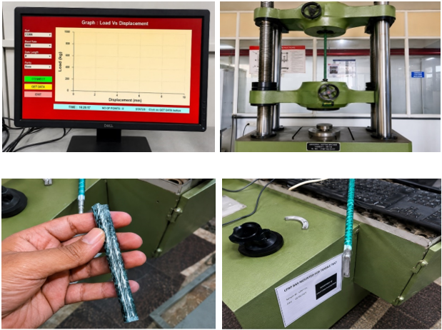
Figure 4. Tensile testing setup, peak-load screen and data-acquisition views.
The images from the tensile test confirm that the material testing was performed with the universal test machine and digital acquisition of data. The images show the specimen clamped in the UTM, the loading-displacement screen, the screen for steel/CFRP data, and the monitoring interface. The heights recorded were also confirmed with the images as the peak forces were recorded at 39.30 kN for steel and 45.95 kN for CFRP. Proper alignment in UTM is crucial since CFRP bars are sensitive to grip crushing, surface degradation, and stress concentration. The images provide evidence that the material properties were observed continuously and not just at the time of failure as the hybrid beam behavior depends on the tensile properties of the materials prior to their embedding into the concrete.
Figure 5. Tensile test load-displacement comparison developed from UTM screen readings.
The load versus displacement diagram compares the steel specimen and the CFRP sample at the material level. The load carried by the steel sample reaches 39.30kN at around 4.70 mm, while CFRP reaches 45.95 kN at about 6.80 mm. The trend shows that CFRP leads to a higher tensile load in the tested condition. However, the graph needs to be analyzed considering the mode of failure of the material involved. Steel fails by yielding, which means that deformation occurs and serves as a warning, while CFRP fail without yielding prior to failure. Thus, the bigger peak load of the CFRP specimen should not be taken as an advantage of the replacement.
The sample photographs of the bars show the state of the CFRP bars and the setup for the experimental testing. One of the photographs shows the surface and broken/processed bar, while the other image shows the mounting of the machine that indicates the position of the specimen when it is subjected to tension. These images are useful because CFRP bars are anisotropic composite materials, whereby the longitudinal fibres bear most of the stress while the resin and surface conditioning play a part in bonding and gripping. Flowing problems during the handling of bars can result in the loss of strength due to splitting whenever the bar is subjected to force. Therefore, these photographs enable tracing all the steps during the experiment.
Figure 7. Four-point bending test arrangement and flexural UTM monitoring.
Images from flexural tests demonstrate the mechanical loading setup that was used to assess beam response. The four-point bending technique is suitable for the current research as it enables the creation of a constant moment zone between the two loading areas, revealing flexural cracks without the influence of shear stresses. These images capture the beam, loading frame and the universal testing machine. The beam is positioned on the supports, the initial load is applied, and the testing process moves from loading increases until the appearance of the first visible crack in the service response, yielding stage, and last stage. The method allows for a direct comparison of the loads at which the first cracks occurred, the maximum load, and the deflection in the mid-span area. In terms of the setup utilized in the conducted experiments, the glass and steel load percentage acts as the only variable in the already known testing arrangements.
3.2.1. Analytical Processing and Performance Parameters
A consistent set of operational parameters allowed for the assessment of all beams on a common technical basis. The load that caused the formation of the first visible flexural crack in the constant-moment zone was defined as the first-crack load. The ultimate load indicated the load at which there was considerably loss of strength or failure, while the ultimate deflection was the mid span deflection at this stage.
The identified values determined strength and deformation but was not sufficient to select the optimum CFRP replacement ratio. A beam may have high capacity or fail suddenly, while another beam may have a lower capacity and greater deformation reserves. As a result, ductility, energy absorption, crack width and stiffness were also quantified. The ductility index indicated the distortion capacity beyond the first nonlinear or yield point. Steel-reinforced beams display ductility due to yielding and cracking. In contrast, CFRP-dominated beams exhibit less ductility due to lack of yielding. Energy that a material absorbs was calculated from the area under the load-deflection curve. This joint assessment explains the preference for B-C50 over the stronger B-C100.
The change in percent for each of the response parameters was calculated with respect to the steel control beam. If Xchas been taken as the control value whereas the value of the hybrid or CFRP specimen will be taken as Xh, then the percentage change is given as [(Xh − Xc)/Xc]×100. So positive values for first crack load and ultimate load indicated the performance improved. A negative value for ductility and deflection indicates the reduction in deformation capacity. This calculation allows for an easier comparison of results due to the absolute values possessing dissimilar units and magnitudes. For instance, the ultimate load improved by 34.1% but ductility reduced by 22.9%.
A joint evaluation provides more insight than focusing only on the final force. Consideration should be given to the width of cracks as it is an important serviceability aspect involved in usability, durability and appearance. The lowest crack width of 0.34 mm was the value of B-C50, which means that steel and CFRP materials are effectively sharing stresses. However, a rise in crack width was characteristic of B-C100 due to various bond mechanisms, limited redistribution and lack of the yielding of steel.
The evaluation of stiffness parameters is based on the initial stiffness of cracking and the final secant stiffness, which can be calculated by dividing the final force by the final deformations. The beams, which have a high amount of CFRP, will have a high level of stiffness and lower deformations, but this does not guarantee ductile behavior because the failure may take place unexpectedly.
3.2.2. Experimental Validity and Control of Variables
Controlling experimental variables is crucial for making a valid comparison. The dimensions of the beam, grade of concrete (M30), curing period, effective support span of deck slab, loading arrangement, spacing of stirrups and top hanger reinforcement are kept constant and only the percentage of steel replaced by CFRP is varied. This method isolates effect of reinforcement composition since minor differences in effective depth, concrete cover, shear span, and concrete quality significantly affects flexural behaviour. Each specimen has four bottom tensile bars, which enables 25% replacement increments to be made without changing the overall bar total.
The criteria for observations are consistent. The load of first visible flexural crack by the test was noted, and load–deflection data collected at same loading stages. The points where cracks happen are marked and photographed when it first cracks. Steel and CFRP bars should be fitted with strain gauges as far as possible to validate steel yielding and the CFRP elastic contribution.
Supporting your technical documents through the photographic evidence of the tensile-test and four-point bending arrangements, the photographic evidence ensures traceability and validation of the experimental setup. Every image must have a suitable caption, along with equipment information and interpretation of response.
A universal design recommendation on the optimal CFRP replacement level is not proposed. Finding will be valid for adopted size of beam M30 concrete and 25% replacement. With the increase of CFRP content, the flexural strength increases but with the reduced steel content, ductility and energy absorption will be reduced. In the present study, the specimen with 50% replacement gives the most balanced response. Further validation is required using larger beams, repeated loading, exposure to environment and numerical modelling before field application.
3.2.3. Result Processing Equations and Decision Logic
The load carrying gain for each specimen was determined by comparing the value of the hybrid or CFRP beam against the steel control value. The formula mentioned was: percentage gain in load = [(Pu,h - Pu,c)/Pu,c] × 100 where Pu,h is the ultimate load of the hybrid or CFRP beam, Pu,c is ultimate load of B-S100. The expression was the same for first crack load and energy absorption. In determining deflection and ductility, negative values were interpreted as reductions because lower ultimate deflection and lower ductility indicate less reserve of deformation energy. Energy absorption consists of the area under the load-deflection curve at which point the ultimate point occurs. This can be approximated in a simplified discrete experimental plot using the trapezoidal rule between two successive load-deflection readings. This parameter is beneficial for hybrid steel–CFRP beams as it penalizes brittle high-load behaviour, and favours a beam that can continue to carry load over a longer deformation path. In the present results, B-C50 beam offers the highest energy absorption of 133 N-m although B-C100 offers the highest ultimate load. To prevent one-side selection, a combined performance index was made. The overall load, energy absorption, ductility, and crack-width response were all considered together. The established decision-making process rewards high load and high energy capacity, but also penalizes low ductility and poor serviceability. This is why the ultimate load of the B-C100 specimen is 31.0 kN but not 1st. B-C50 specimen combines 24.8 kN load, 2.7 ductility index, 133 N-m energy absorption and indicative crack width is lower. Hence, the better overall profile achieved by this specimen. An engineering equilibrium was used to select the ideal replacement ratio. Strengthening a material doesn’t make it acceptable if the replacement level doesn’t allow for normal use of the material. The structure should control cracks, warn before failure, and not respond abruptly like a brittle structure. The reasoning structure adopted in this work follows the larger understanding that hybrids are better suited for any resulting member. Steel is retained for ductility and deformation reserve, CFRP is introduced for corrosion resistance and enhancement of tensile capacity. The configuration 700 mm × 100 mm × 100 mm of beams with 50% replacement level is the most suitable.
4. Results and Discussion
There are two types of testing methods employed in this study. The first type assesses the criteria for the capacity while the second type assesses the criteria for usability. First crack indicates the ability of a structure to crack when placed under tension. Ultimate load shows the load-bearing capability of a component. Ultimate deflection, ductility index, and energy absorption show the total deformation sustained by the component before failure. Cracking factors and stiffness indices are then used to determine serviceability criteria. A general grading system is used to decide the level of the substitution. The results indicate that an increase in CFRP percentage in concrete increases the strength but causes a decrease in ductility with high percentages of CFRP. Thus, B-C50 is estimated to be normal while B-C100 is considered to carry the maximum load.
Table 7. Comparative result matrix for first crack load, ultimate load and deflection.
Specimen | CFRP replacement | First crack load (kN) | Ultimate load (kN) | Ultimate deflection (mm) |
B-S100 | 0% | 4.2 | 18.5 | 10.5 |
B-C25 | 25% | 4.5 | 21.2 | 9.8 |
B-C50 | 50% | 4.8 | 24.8 | 9.0 |
B-C75 | 75% | 5.1 | 27.5 | 7.8 |
B-C100 | 100% | 5.2 | 31.0 | 6.2 |
The matrix of results indicates a consistent upward trend for both first crack load and ultimate load as the CFRP content in steel rises. The first crack load rises from 4.2 kN for B-S100 to a larger value of 5.2 kN in B-C100, which shows that the tensile strength of the sample increased over the time before the first crack became visible. The ultimate load shows an astonishing rise from 18.5 kN to 31.0 kN since CFRP increases tensile capacity even after the formation of the first crack. However, along with the increase in the content of CFRP, the ultimate deflection goes down from 10.5 mm to 6.2 mm. The evident data point out the main drawback of hybrid systems: CFRP increases the load-bearing capacity whereas yielding of steel reduces deformity. The ultimate load in B-C50 exceeds 24.8 kN while the average deflection is equal to 9.0 mm.
Table 8. Ductility, energy absorption and expected failure mode.
Specimen | Ductility index | Energy absorption (N-m) | Expected failure mode |
B-S100 | 3.5 | 118 | Steel yielding followed by concrete crushing |
B-C25 | 3.1 | 126 | Steel yielding with elastic CFRP contribution |
B-C50 | 2.7 | 133 | Balanced hybrid flexural failure |
B-C75 | 2.0 | 120 | Reduced ductility; CFRP-dominated response |
B-C100 | 1.2 | 95 | Concrete crushing or CFRP rupture with brittle tendency |
Low ductility and energy absorption values indicate why full CFRP replacement is suboptimal. The highest ductility index of 3.5 was recorded by B-S100, which indicates that the yielding of steel provides significant deformation reserves. The behaviour of B-C25 was similar, with a ductility index of 3.1 and the energy absorption value equal to 126 N·m. The ductility index for B-C50 was 2.7 and energy absorption 126 N·m, resulting in satisfactory strength-deformation characteristics. However, the ductility value for B-C75 dropped to 2.0 and to only 1.2 for B-C100, whose absorption capacity was limited to 95 N·m. Thus, while CFRP-rich girders perform better in terms of load capacity, they also fail without warning.
Figure 8. Load-deflection behaviour of steel, hybrid and CFRP beams.
The load-deflection curves illustrate all the bending characteristics of the five specimens. The steel specimen B-S100 can withstand a maximum load of 18.5 kN, which means it has the maximum deformation and the minimum carrying capacity, respectively. In the case of B-C25 with 25 percent of CFRP, a maximum load of 21.2 kN is reached, but the specimen does not have significant deformation which means there is modest load gain without severe deformation loss. The next specimen B-C50 reaches 24.8 kN at a deflection of 9.0 mm, showing a smooth curve and thus evidence of the hybrid reaction. The specimen B-C75 reaches an even higher load of 27.5 kN, with deflection of 7.8 mm. The specimen B-C100 withstands a load of 31.0 kN but suffers from a maximum displacement of 6.2 mm. In summary, the results show that the decrease in the carrying capacity is counterbalanced by the increase in the carrying capacity of the specimen B-C50.
Figure 9. First crack load comparison.
Visible cracking starts to appear later due to the use of CFRP. The first beam to crack is the B-S100, which cracks at 4.2 kN. The B-C25 shows an increased cracking load at 4.5 kN, with the B-C50 reaching 4.8 kN. Meanwhile, the first cracks develop at 5.1 kN for the B-C75 and for the B-C100 an even higher cracking load is reached at 5.2 kN. This explains why the differences exists, CFRP material helps because it introduces higher tensile strength when the concrete tensile zone starts working less. The difference between first cracking loads is 1 kN, which is equal to approx. 23.8%. However, the first cracking load needs to be analyzed with regards to post-cracking behavior. High cracking resistance works well for serviceability, but a high amount of CFRP may negatively affect ductility.
Figure 10. Ultimate load comparison.
The ultimate load chart presents the most obvious strength benefit of the use of CFRP. The ultimate load goes from 18.5 kN for the steel reference beam to 21.2 kN for 25% CFRP, to 24.8 kN for 50% CFRP, to 27.5 kN for 75% CFRP, and to 31.0 kN for completely replacing steel beams. The improvement regarding B-S100 is accordingly 14.6%, 34.1%, 48.6%, and 67.6%. This shows that CFRP bars can effectively lead to improvement in flexural resistance at the tensile zone. However, it is important to remember that decision based on ultimate load alone is not enough. Though the fully CFRP beam shows the highest capacity, it also has the lowest ductility and energy absorption. Therefore, 50% replacement seems to give an optimal solution in general applications.
Figure 11. Ultimate deflection comparison.
Increased CFRP substitution is associated with the subsequent decrease of maximum deflection. For example, B-S100 has a deflection of 10.5 mm at failure; B-C25 yields a deflection of 9.8 mm; B-C50 records 9.0 mm of deflection; B-C75 has a deflection of 7.8 mm; and B-C100 has the deflection of just 6.2 mm Therefore, the reductions in comparison to the reference steel specimen equal 6.7%, 14.3%, 25.7%, and 41.0% correspondingly. This fact demonstrates that the contribution of yielding of steel bars is being lost and the behavior of CFRP reinforcement is more elastic-brittle. Despite the fact that low deflection looks good from the perspective of working loads, the lack of ultimate deflection means that a warning prior to the destruction is not provided. In treatment of classical reinforced concrete design methods, maximum deflection is taken into account. Therefore, B-C100 is not the preferable choice of options even though it resists a maximum load, whereas B-C50 seems to keep a reasonable compromise with its ultimate deflection of 9.0 mm.
Figure 12. Ductility index comparison.
The graph of the ductility index illustrates the main issue regarding excessive use of CFRP. The ductility index of beam B-S100 made of steel is equal to 3.5, which indicates that it has the maximum reserve of deformation. The ductility index of beam B-C25 declines moderately to 3.1, and beam B-C50 reaches the value of 2.7, which is still satisfactory for the hybrid beam according to this comparative scale. However, after that, there is a sharp decline of the value to 2.0 for beam B-C75 and to 1.2 for beam B-C100. Therefore, the fully-made CFRP beam behaves in more brittle manner compared to reinforcement made of the metal since CFRP reinforcement does not experience any yielding before breaking. This graph is very important in terms of choosing the optimal beam. Although the ultimate load continuously increases with the increase in the percentage of CFRP, the loss of ductility becomes critical after the 50% displacement, which is why beam B-C50 is preferred in comparison with beams B-C75 and B-C100.
Figure 13. Energy absorption comparison.
The term energy absorption refers to the area under the load versus deflection response. It tells how much work a structure can take before breaking. B-S100 has an absorption figure of 118 N-m, whereas B-C25 has a figure of 126 N-m, and the highest absorption figure for B-C50 is equal to 133 N-m. This shows that when CFRP is replaced moderately, the absorption is improved as well, and the beneficial deformation is retained. B-C75 has the energy absorption figure of 120 N-m, while B-C100 has the least absorption at 95 N-m showing that although the maximum failure load is achieved by B-C100, high energy absorption is better than having just high peak load.
Figure 14. Effect of CFRP replacement on ultimate load.
The graph of replacement vs. load shows the strength trend dependent on the CFRP percentage. It appears linear, with values increasing from 18.5 kN to 31.0 kN. It can be seen that the significant growth indicates that high percentages of CFRP result in improved tension and flexure capacity. B-C50 at 24.8 kN is already 34.1% stronger than the control sample, but still contains more steel than 75 and 100% CFRP samples. This aspect must be taken into account in design since it proves that high capacity is achieved with a partial replacement of material. From a practical point of view, the graph gives evidence that CFRP can be used in cases when there is a need to gain strength and durability without the need for ductile behavior.
Figure 15. Effect of CFRP replacement on ductility.
The graph of substitution against ductility reveals that as the amount of CFRP rises, ductility descends in a continuous manner. Initially at 0% substitution, ductility is 3.5 and by 100% it falls down to just 1.2. Beyond 50% substitution, the slope falls sharply as there is insufficient steel present to yield. Ductility at various percentages follows a pattern that is corroborated by the stress-strain behavior of both materials. Steel exhibits elastic-plastic behavior and strains can be redistributed after yielding, while CFRP remains elastic until rupture or until it fails under compression. In this regard, the graph indicates the need for caution concerning ductility to make sure it is still within acceptable range as per design requirements, although increasing CFRP content raises durability and strength levels.
Figure 16. Indicative crack-width comparison.
The crack width graph gives a serviceability view on hybrid beams. In the case of the control beam, the resulting maximum crack is considered to be 0.42 mm. In the case of B-C25 this drops to 0.39 mm and in the case of B-C50 it is further reduced to 0.34 mm, showing that the control over the crack width improves with the use of CFRP reinforcement. In the case of B-C75 there is a slight increase to 0.36 mm while B-C100 reaches 0.48 mm. The fact that the highest crack width occurs in the case of a fully CFRP beam agrees with the reduced ductility and different bonding behaviour of CFRP reinforcement. Therefore, the serviceability results don’t simply correspond to ultimate load. In the case of B-C50, the specimen performs best because it shows the lowest maximum crack width while still maintaining a balanced contribution of steel.
Figure 17. Stiffness indices from load-deflection data.
Stiffness measures compare the initial cracking stiffness with the final secant stiffness. Generally, the initial cracking stiffness increases with the use of CFRP because of the better mechanical properties of tensile CFRP reinforcement. However, final secant stiffness should also be evaluated in conjunction with the corresponding final deflection and ductility. It can be observed that the fully CFRP beam has a high load-to-deflection ratio at the point of failure. However, this does not provide proper safety, as it means that the beam has a low level of deflection capacity. In comparison, hybrid beams show a more balanced stiffness profile. The beam B-C50 has a sufficient initial stiffness to behave appropriately during the service and a proper level of deflection capacity to be classified as ductile unlike B-C100. The graph proves that stiffness should be evaluated together with strength and ductility while choosing the amount of replacement.
Figure 18. Combined optimum-replacement performance index.
The consolidated performance index is used to obtain one value that makes it possible to compare strength, energy absorption, ductility and serviceability responses. The performance of B-S100 is 71.1, B-C25 reports score equal to 78.8, the highest value of 87.3 belongs to B-C50, 79.9 is the performance score of B-C75 and B-C100 achieves 61.4. The ranks demonstrate the clearly observed disadvantage of total performance of the entirely CFRP solution. In spite of the fact that the highest load capacity values were shown by this option, its ductility and energy absorption impact performance negatively. Performance of B-C50 is the best in terms of ultimate load increase (34.1%), energy absorption (133 N-m) and ductility (2.7) as well as the smallest indicative crack width. According to the performance index graph, it is evident that B-C50 is the best solution for replacing 50% of the overall amount of CFRP in the present beam system.
Table 9. Percentage change relative to steel control beam B-S100.
Specimen | First crack change | Ultimate load change | Deflection change | Ductility change | Energy change |
B-S100 | 0.0% | 0.0% | 0.0% | 0.0% | 0.0% |
B-C25 | 7.1% | 14.6% | -6.7% | -11.4% | 6.8% |
B-C50 | 14.3% | 34.1% | -14.3% | -22.9% | 12.7% |
B-C75 | 21.4% | 48.6% | -25.7% | -42.9% | 1.7% |
B-C100 | 23.8% | 67.6% | -41.0% | -65.7% | -19.5% |
The comparison of percentages refers to the compromise that comes with CFRP replacement. B-C50 has an increase in first-crack and ultimate loads by 14.3% and 34.1% respectively, while at the same time the ultimate deflection and ductility decreased by 14.3% and 22.9% respectively. In the same sense, energy absorption shows 12.7% improvement.
On the contrary, while B-C100 increases the ultimate load by 67.6%, it decreases ductility by 65.7% and energy absorption by 19.5%. Very much like B-C75, where ductility drops by 42.9% and energy absorption increases only by 1.7%. This case shows that the assessment of CFRP efficiency cannot be measured only by strength gain. When considering strength, deformation capacity and energy absorption, B-C50 provides the most proper replacement configuration.
Table 10. Optimum replacement decision matrix.
Specimen | CFRP replacement | Ultimate load (kN) | Ultimate deflection (mm) | Ductility | Energy (N-m) | Performance index | Rank |
B-S100 | 0% | 18.5 | 10.5 | 3.5 | 118 | 71.1 | 3 |
B-C25 | 25% | 21.2 | 9.8 | 3.1 | 126 | 78.8 | 2 |
B-C50 | 50% | 24.8 | 9.0 | 2.7 | 133 | 87.3 | 1 |
B-C75 | 75% | 27.5 | 7.8 | 2.0 | 120 | 79.9 | 4 |
B-C100 | 100% | 31.0 | 6.2 | 1.2 | 95 | 61.4 | 5 |
A decision matrix is used to gather results and show them together in one selection table. The decision matrix results show that B-C100 has the highest load of 31.0 kN, although its capacity shows lower results in ultimate deflection, ductility index, and energy absorption. B-C75 also provides a good load but has low ductility. B-S100 shows good results in terms of deflection but has low resistance to load and no positive influence of CFRP durability.
B-C25 gives moderate results while B-C50 shows the most combined score of 87.3. Its load capacity of 24.8 kN, deflection of 9.0 mm, ductility index of 2.7, and energy absorption of 133 N-m prove that the contribution of steel and CFRP is also good in this case. The final recommendation is that it is good to replace 50% of original material.
Figure 19. Uploaded stress-strain graph from reinforcement tension test file.
The stress-strain graph provides significant support to the understanding of the material in terms of its yield behaviour. It shows the presence of four stages – the initial rise, yield point, the area of constant strain and finally, failure. This implies that the steel reinforcement is not a brittle material that fails without any warning. During the tests conducted on beams made of steel, this ductility is important for being able to detect the crack propagation. The graph thereby clarifies why beam B-S100 and B-C25 with significant amounts of steel show more ductility. At the same time, beams containing a larger amount of steel show lower ultimate load than beams that have CFRP in them. However, beam B-C50 is the only beam that has both mechanisms working (steel and CFRP).
Limitations
The study incorporates only monotonic flexural testing of small-scale beams. It does not encompass fatigue, cyclic loading, sustained loading, creep, alkaline ageing, chloride exposure, freeze–thaw action or elevated temperatures. CFRP is resistant to corrosion but its bond interface and resin matrix may weaken over the long term due to environmental exposure. The research employs only a single-grade concrete and beam size so that other grades, spans, reinforcement ratios, and bar diameters should be considered to develop generalized design equations.
Accordingly, the results are seen as laboratory trends rather than design guidelines. The mean value, standard deviation and confidence intervals should be determined by testing at least three specimens for each replacement ratio in future work. Strain gauges are to be placed on the steel bars, CFRP bars and the concrete compression zone to monitor steel yielding, CFRP strain and neutral-axis movement. Crack-width and crack-spacing measurements may also benefit from digital image correlation. In the end, it is important to validate experimental capacities against ACI 440, CSA S806, IS 456 and relevant FRP design models for generating reliable design-oriented recommendations.
5. Conclusions
1) The results of the experimental comparison indicate that replacing SFRP leads to better crack and ultimate strength values. The first crack load for the steel reference beam was 4.2 kN, while that for the fully SFRP beam was 5.2 kN. The ultimate load was 18.5 kN in the case of the steel control beam, whereas that for the fully SFRP beam was 31.0 kN.
2) The rise in strength coincided with the distinct decrease in deformation capacity. Maximum deflection decreased from 10.5 mm for B-S100 to 6.2 mm for B-C100, and the ductility index decreased from 3.5 to 1.2 with the increase in the percentage of CFRP replacement.
3) The B-C50 beam containing 50% CFRP gave the best overall performance with the capacity to support a load of 24.8 kN, deflect 9.0 mm, achieve a ductility index of 2.7, and the most energy absorption of 133 N-m.
4) Crack serviceability and energy absorption showed that maximum CFRP percentage does not always mean maximum advantage. B-C100 has maximum strength but produces less energy absorption of 95 N-m and is more prone to brittle failure.
5) The M30 concrete with 394 kg/m3 of cement, 197 L/m3 of water, 787 kg/m3 of fine aggregate and 1082 kg/m3 of coarse aggregate produced uniform concrete for all beams.
6) The recommendation for a beam of the tested sizes and distribution of materials is to use 50% replacement of CFRP in order to achieve more strength with acceptable ductility, crack control and energy absorption performance.
Abbreviations
CFRP | Carbon Fiber-Reinforced Polymer |
FRP | Fiber-Reinforced Polymer |
RC | Reinforced Concrete |
UTM | Universal Testing Machine |
LVDT | Linear Variable Differential Transformer |
ACI | American Concrete Institute |
ASTM | American Society for Testing and Materials |
IS | Indian Standard |
w/c | Water–Cement Ratio |
Author Contributions
Anas Ali Jabir Ali Sayyed: Conceptualization, Data curation, Formal Analysis, Investigation, Methodology, Visualization, Writing – original draft
Raju Narwade: Conceptualization, Methodology, Project administration, Supervision, Validation, Writing – review & editing
Karthik Nagarajan: Formal Analysis, Resources, Validation, Writing – review & editing
Asir Khan: Formal Analysis, Validation, Writing – review & editing
Conflicts of Interest
The authors declare no conflicts of interest.
References
| [1] |
B. WEI, X. HE, M. Zhou, H. Wang, and J. He, "Experimental study on flexural behaviors of FRP and steel bars hybrid reinforced concrete beams," Case Studies in Construction Materials, vol. 20, Art. no. e02759, 2024,
https://doi.org/10.1016/j.cscm.2023.e02759.
|
| [2] |
A. Jahami and C. A. Issa, "An updated review on the effect of CFRP on flexural performance of reinforced concrete beams," International Journal of Concrete Structures and Materials, vol. 18, 2024,
https://doi.org/10.1186/s40069-023-00651-y
|
| [3] |
K. Megahed, "Predicting flexural strength of hybrid FRP-steel reinforced beams using symbolic regression and ML techniques," Scientific Reports, vol. 15, Art. no. 20277, 2025,
https://doi.org/10.1038/s41598-025-05775-7
|
| [4] |
T. Zhang, D. Gao, and C. Xue, "Flexural strength prediction of concrete beams reinforced with hybrid FRP and steel bars based on machine learning," Structures, vol. 65, Art. no. 106652, 2024,
https://doi.org/10.1016/j.istruc.2024.106652
|
| [5] |
Y. Zhou, G. Wu, and X. Lu, "Flexural strength design of hybrid FRP-steel reinforced concrete beams," Materials, vol. 14, no. 21, Art. no. 6400, 2021,
https://doi.org/10.3390/ma14216400
|
| [6] |
Y. Zhou, G. Wu, and X. Lu, "A general numerical model for predicting flexural behavior of hybrid FRP-steel reinforced concrete beams," Engineering Structures, vol. 239, Art. no. 112293, 2021,
https://doi.org/10.1016/j.engstruct.2021.112293
|
| [7] |
Y. Yang, D. Pan, G. Wu, and D. Cao, "A new design method of the equivalent stress-strain relationship for hybrid FRP bar and steel bar reinforced concrete beams," Composite Structures, vol. 270, Art. no. 114099, 2021,
https://doi.org/10.1016/j.compstruct.2021.114099
|
| [8] |
X. Ruan, C. Lu, K. Xu, G. Xuan, and M. Ni, "Flexural behavior and serviceability of concrete beams hybrid-reinforced with GFRP bars and steel bars," Composite Structures, vol. 235, Art. no. 111772, 2020.
https://doi.org/10.1016/j.compstruct.2019.111772
|
| [9] |
H. Abbas, A. Abadel, T. H. Almusallam, and Y. A. Al-Salloum, "Experimental and analytical study of flexural performance of concrete beams reinforced with hybrid of GFRP and steel rebars," Engineering Failure Analysis, vol. 138, Art. no. 106397, 2022,
https://doi.org/10.1016/j.engfailanal.2022.106397
|
| [10] |
A. Hussein, H. Huang, Y. Okuno, and Z. Wu, "Experimental and numerical parametric study on flexural behavior of concrete beams reinforced with hybrid combinations of steel and BFRP bars," Composite Structures, vol. 302, Art. no. 116230, 2022,
https://doi.org/10.1016/j.compstruct.2022.116230
|
| [11] |
X. Wang, S. Liu, Y. Shi, Z. Wu, and W. He, "Integrated high-performance concrete beams reinforced with hybrid BFRP and steel bars," Journal of Structural Engineering, vol. 148, no. 1, Art. no. 04021235, 2022.
|
| [12] |
S. Kartal, I. Kalkan, A. Beycioglu, and M. Dobiszewska, "Load-deflection behavior of over- and under-reinforced concrete beams with hybrid FRP-steel reinforcements," Materials, vol. 14, no. 18, Art. no. 5341, 2021,
https://doi.org/10.3390/ma14185341
|
| [13] |
D. P. Nguyen and V. Q. Dang, "Limiting reinforcement ratios for hybrid GFRP/steel reinforced concrete beams," International Journal of Engineering and Technology Innovation, vol. 11, no. 1, pp. 1-11, 2021,
https://doi.org/10.46604/ijeti.2021.6660
|
| [14] |
N. Duy and D. Hiep, "Analytical identification of failure modes and design-oriented formulations in hybrid FRP/steel reinforced concrete beams," International Journal of Civil Engineering, vol. 21, pp. 727-750, 2023,
https://doi.org/10.1007/s40999-022-00796-z
|
| [15] |
S. Liu, X. Wang, Y. M. S. Ali, C. Su, and Z. Wu, "Flexural behavior and design of under-reinforced concrete beams with BFRP and steel bars," Engineering Structures, vol. 263, Art. no. 114386, 2022,
https://doi.org/10.1016/j.engstruct.2022.114386
|
| [16] |
Z. Peng, X. Jiajing, Q. Wenjun, and H. Hao, "Experimental study of fatigue flexural performance of concrete beams reinforced with hybrid GFRP and steel bars," Journal of Composites for Construction, vol. 21, no. 5, Art. no. 04017036, 2017,
https://doi.org/10.1061/(ASCE)CC.1943-5614.0000817
|
| [17] |
Z. Sun et al., "Experimental study on the flexural behavior of concrete beams reinforced with bundled hybrid steel/FRP bars," Engineering Structures, vol. 197, Art. no. 109443, 2019,
https://doi.org/10.1016/j.engstruct.2019.109443
|
| [18] |
G. B. Maranan et al., "Flexural behavior of geopolymer-concrete beams longitudinally reinforced with GFRP and steel hybrid reinforcements," Engineering Structures, vol. 182, pp. 141-152, 2019.
https://doi.org/10.1016/j.engstruct.2018.12.073
|
| [19] |
W. Qu, X. Zhang, and H. Huang, "Flexural behavior of concrete beams reinforced with hybrid GFRP and steel bars," Journal of Composites for Construction, vol. 13, no. 5, pp. 350-359, 2009,
https://doi.org/10.1061/(ASCE)CC.1943-5614.0000035
|
| [20] |
D. Lau and H. J. Pam, "Experimental study of hybrid FRP reinforced concrete beams," Engineering Structures, vol. 32, no. 12, pp. 3857-3865, 2010,
https://doi.org/10.1016/j.engstruct.2010.08.028
|
| [21] |
A. El Refai, F. Abed, and A. Al-Rahmani, "Structural performance and serviceability of concrete beams reinforced with hybrid GFRP and steel bars," Construction and Building Materials, vol. 96, pp. 518-529, 2015.
https://doi.org/10.1016/j.conbuildmat.2015.08.063
|
| [22] |
W. Ge, J. Zhang, D. Cao, and Y. Tu, "Flexural behaviors of hybrid concrete beams reinforced with BFRP bars and steel bars," Construction and Building Materials, vol. 87, pp. 28-37, 2015,
https://doi.org/10.1016/j.conbuildmat.2015.03.113
|
| [23] |
ACI Committee 440, Building Code Requirements for Structural Concrete Reinforced with Glass Fiber-Reinforced Polymer Bars and Commentary (ACI 440.11-22). Farmington Hills, MI, USA: American Concrete Institute, 2022.
|
| [24] |
ACI Committee 440, Guide for the Design and Construction of Structural Concrete Reinforced with Fiber-Reinforced Polymer Bars (ACI 440.1R-15). Farmington Hills, MI, USA: American Concrete Institute, 2015.
|
| [25] |
CSA Group, Design and Construction of Building Structures with Fibre-Reinforced Polymers, CSA S806-12. Toronto, ON, Canada: CSA Group, 2012.
|
| [26] |
Bureau of Indian Standards, Concrete Mix Proportioning: Guidelines, IS 10262: 2019. New Delhi, India: BIS, 2019.
|
| [27] |
Bureau of Indian Standards, Plain and Reinforced Concrete: Code of Practice, IS 456: 2000. New Delhi, India: BIS, 2000.
|
| [28] |
Bureau of Indian Standards, Methods of Tests for Strength of Concrete, IS 516: 1959. New Delhi, India: BIS, 1959.
|
| [29] |
ASTM International, Standard Test Method for Tensile Properties of Fiber Reinforced Polymer Matrix Composite Bars, ASTM D7205/D7205M. West Conshohocken, PA, USA: ASTM International, 2021.
|
| [30] |
ASTM International, Standard Test Method for Flexural Strength of Concrete Using Simple Beam with Third-Point Loading, ASTM C78/C78M. West Conshohocken, PA, USA: ASTM International, 2022.
|
Cite This Article
-
APA Style
Sayyed, A. A. J. A., Narwade, R., Nagarajan, K., Khan, A. (2026). Experimental Investigation on Partial Replacement of Steel Reinforcement by CFRP Bars in Reinforced Concrete Beams. Advances in Materials, 15(3), 110-131. https://doi.org/10.11648/j.am.20261503.14
 Copy
|
Copy
|
 Download
ACS Style
Sayyed, A. A. J. A.; Narwade, R.; Nagarajan, K.; Khan, A. Experimental Investigation on Partial Replacement of Steel Reinforcement by CFRP Bars in Reinforced Concrete Beams. Adv. Mater. 2026, 15(3), 110-131. doi: 10.11648/j.am.20261503.14
Copy
|
Download
AMA Style
Sayyed AAJA, Narwade R, Nagarajan K, Khan A. Experimental Investigation on Partial Replacement of Steel Reinforcement by CFRP Bars in Reinforced Concrete Beams. Adv Mater. 2026;15(3):110-131. doi: 10.11648/j.am.20261503.14
Copy
|
Download
-
@article{10.11648/j.am.20261503.14,
  author = {Anas Ali Jabir Ali Sayyed and Raju Narwade and Karthik Nagarajan and Asir Khan},
  title = {Experimental Investigation on Partial Replacement of Steel Reinforcement by CFRP Bars in Reinforced Concrete Beams},
  journal = {Advances in Materials},
  volume = {15},
  number = {3},
  pages = {110-131},
  doi = {10.11648/j.am.20261503.14},
  url = {https://doi.org/10.11648/j.am.20261503.14},
  eprint = {https://article.sciencepublishinggroup.com/pdf/10.11648.j.am.20261503.14},
  abstract = {The corrosion of conventional steel reinforcement remains a major durability concern in reinforced concrete members exposed to chlorides, carbonation, moisture and industrial chemicals, because progressive section loss and bond deterioration can reduce stiffness, serviceability and structural reliability. Carbon fiber-reinforced polymer (CFRP) bars provide high tensile strength, low density and excellent resistance to electrochemical corrosion; however, their linear-elastic response up to rupture and comparatively different bond and stiffness characteristics can produce brittle failure and limited warning when they are used as the sole longitudinal reinforcement. The present study experimentally investigates partial replacement of steel tensile reinforcement by CFRP bars in reinforced concrete beams, with the objective of identifying a hybrid reinforcement ratio that improves strength and durability while retaining an acceptable level of deformation capacity. Five M30 concrete beam specimens, each measuring 700 mm x 100 mm x 100 mm, were prepared with constant geometry, concrete grade, loading arrangement and total number of bottom tensile bars. The specimens B-S100, B-C25, B-C50, B-C75 and B-C100 represented 0%, 25%, 50%, 75% and 100% CFRP replacement, respectively. The experimental programme comprised M30 mix proportioning, reinforcement cage fabrication, tensile characterization of steel and CFRP bars, 28-day curing and four-point flexural testing in accordance with the general principles of relevant concrete and composite testing standards. During testing, first-crack load, ultimate load, mid-span deflection, ductility index, energy absorption, stiffness, crack development and expected failure characteristics were evaluated. The adopted M30 mix contained 394 kg/m3 cement, 197 L/m3 water, 787 kg/m3 fine aggregate and 1082 kg/m3 coarse aggregate at a water-cement ratio of 0.50. Material testing indicated a peak load of 39.30 kN at 4.70 mm displacement for the steel sample and 45.95 kN at 6.80 mm for the CFRP sample, confirming the higher tensile resistance of CFRP while emphasizing the need to preserve the yielding contribution of steel in hybrid members. The beam results showed a systematic increase in first-crack load from 4.2 kN for B-S100 to 5.2 kN for B-C100 and an increase in ultimate load from 18.50 kN to 31.00 kN. Conversely, ultimate deflection reduced from 10.5 mm to 6.2 mm and the ductility index decreased from 3.50 to 1.20 as CFRP replacement increased. Among the hybrid configurations, B-C50 developed an ultimate load of 24.80 kN, an ultimate deflection of 9.00 mm, a ductility index of 2.70 and the maximum energy absorption of 133 N-m. It also provided the most favorable combined response in terms of strength enhancement, crack control, deformation reserve and energy dissipation. The findings demonstrate that full CFRP replacement maximizes flexural capacity but substantially reduces ductile warning, whereas moderate hybridization permits the complementary use of steel yielding and CFRP tensile resistance, as reported in previous hybrid beam research. Accordingly, 50% CFRP replacement is recommended as the optimum configuration for the present small-scale beam system. This recommendation is limited to the adopted geometry, material properties and test conditions, and should be validated through replicated tests, larger specimens, long-term durability exposure and numerical modelling before application to full-scale structural design.},
 year = {2026}
}
Copy
|
Download
-
TY  - JOUR
T1  - Experimental Investigation on Partial Replacement of Steel Reinforcement by CFRP Bars in Reinforced Concrete Beams
AU  - Anas Ali Jabir Ali Sayyed
AU  - Raju Narwade
AU  - Karthik Nagarajan
AU  - Asir Khan
Y1  - 2026/08/24
PY  - 2026
N1  - https://doi.org/10.11648/j.am.20261503.14
DO  - 10.11648/j.am.20261503.14
T2  - Advances in Materials
JF  - Advances in Materials
JO  - Advances in Materials
SP  - 110
EP  - 131
PB  - Science Publishing Group
SN  - 2327-252X
UR  - https://doi.org/10.11648/j.am.20261503.14
AB  - The corrosion of conventional steel reinforcement remains a major durability concern in reinforced concrete members exposed to chlorides, carbonation, moisture and industrial chemicals, because progressive section loss and bond deterioration can reduce stiffness, serviceability and structural reliability. Carbon fiber-reinforced polymer (CFRP) bars provide high tensile strength, low density and excellent resistance to electrochemical corrosion; however, their linear-elastic response up to rupture and comparatively different bond and stiffness characteristics can produce brittle failure and limited warning when they are used as the sole longitudinal reinforcement. The present study experimentally investigates partial replacement of steel tensile reinforcement by CFRP bars in reinforced concrete beams, with the objective of identifying a hybrid reinforcement ratio that improves strength and durability while retaining an acceptable level of deformation capacity. Five M30 concrete beam specimens, each measuring 700 mm x 100 mm x 100 mm, were prepared with constant geometry, concrete grade, loading arrangement and total number of bottom tensile bars. The specimens B-S100, B-C25, B-C50, B-C75 and B-C100 represented 0%, 25%, 50%, 75% and 100% CFRP replacement, respectively. The experimental programme comprised M30 mix proportioning, reinforcement cage fabrication, tensile characterization of steel and CFRP bars, 28-day curing and four-point flexural testing in accordance with the general principles of relevant concrete and composite testing standards. During testing, first-crack load, ultimate load, mid-span deflection, ductility index, energy absorption, stiffness, crack development and expected failure characteristics were evaluated. The adopted M30 mix contained 394 kg/m3 cement, 197 L/m3 water, 787 kg/m3 fine aggregate and 1082 kg/m3 coarse aggregate at a water-cement ratio of 0.50. Material testing indicated a peak load of 39.30 kN at 4.70 mm displacement for the steel sample and 45.95 kN at 6.80 mm for the CFRP sample, confirming the higher tensile resistance of CFRP while emphasizing the need to preserve the yielding contribution of steel in hybrid members. The beam results showed a systematic increase in first-crack load from 4.2 kN for B-S100 to 5.2 kN for B-C100 and an increase in ultimate load from 18.50 kN to 31.00 kN. Conversely, ultimate deflection reduced from 10.5 mm to 6.2 mm and the ductility index decreased from 3.50 to 1.20 as CFRP replacement increased. Among the hybrid configurations, B-C50 developed an ultimate load of 24.80 kN, an ultimate deflection of 9.00 mm, a ductility index of 2.70 and the maximum energy absorption of 133 N-m. It also provided the most favorable combined response in terms of strength enhancement, crack control, deformation reserve and energy dissipation. The findings demonstrate that full CFRP replacement maximizes flexural capacity but substantially reduces ductile warning, whereas moderate hybridization permits the complementary use of steel yielding and CFRP tensile resistance, as reported in previous hybrid beam research. Accordingly, 50% CFRP replacement is recommended as the optimum configuration for the present small-scale beam system. This recommendation is limited to the adopted geometry, material properties and test conditions, and should be validated through replicated tests, larger specimens, long-term durability exposure and numerical modelling before application to full-scale structural design.
VL  - 15
IS  - 3
ER  -
Copy
|
Download

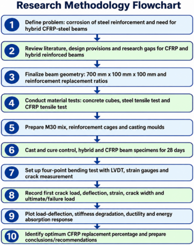
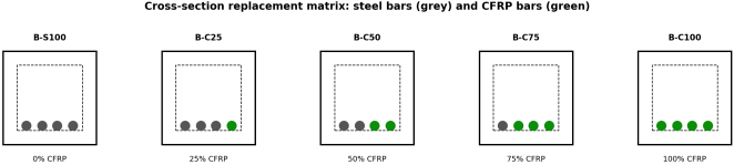
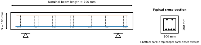
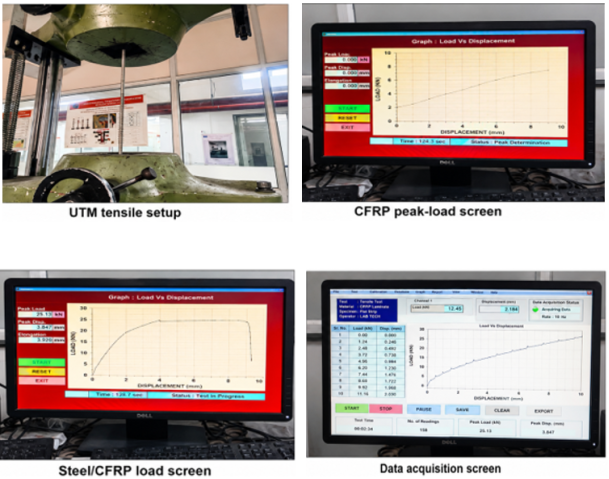
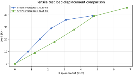
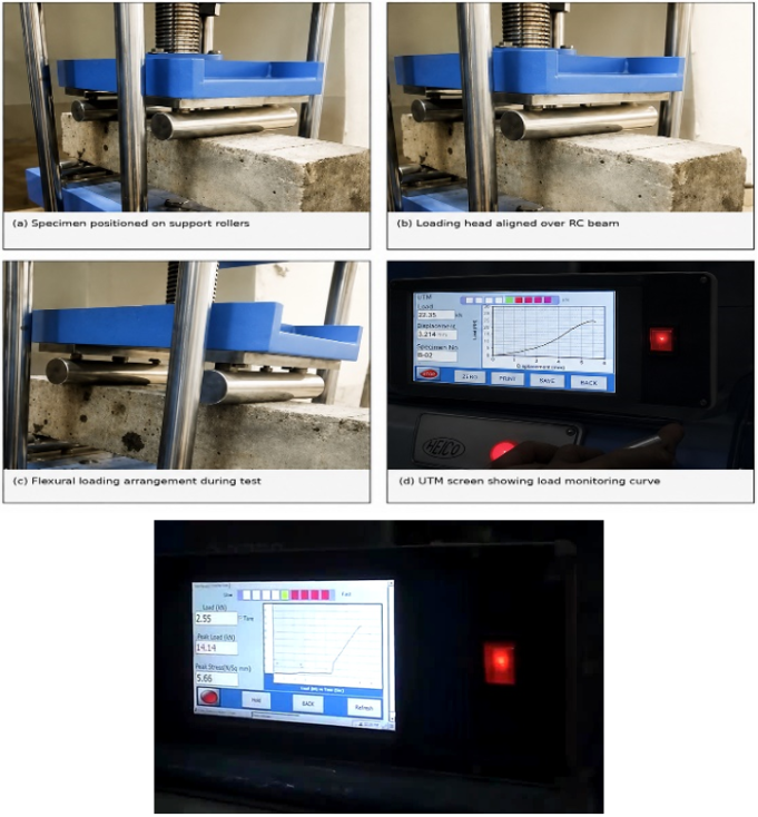
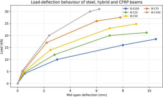
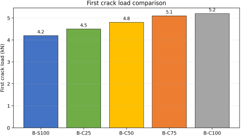
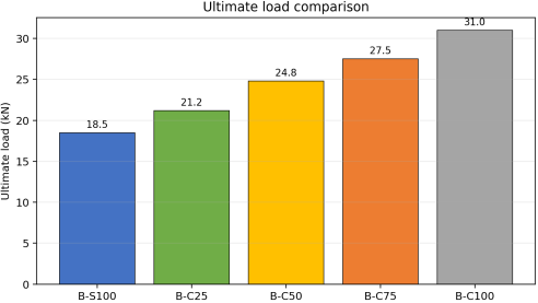
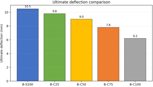
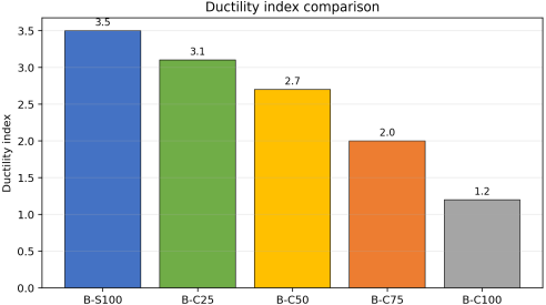
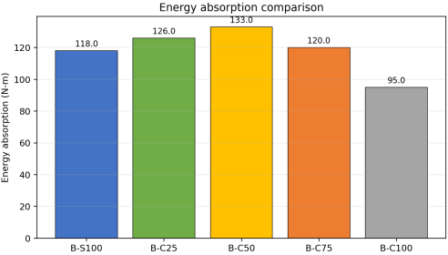
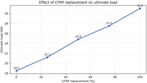
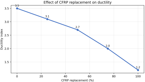
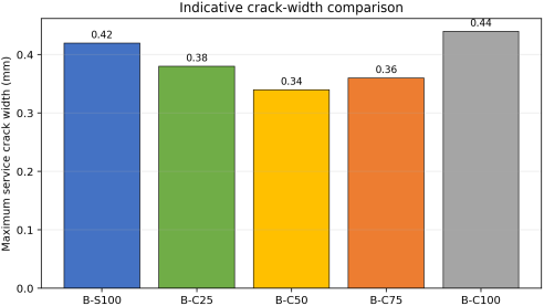
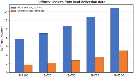
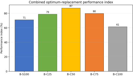
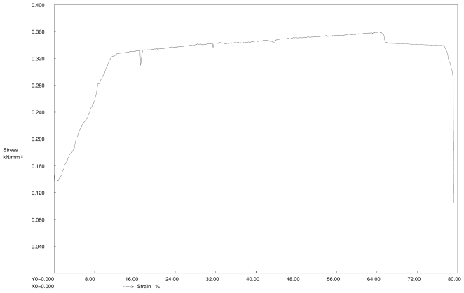




 Share This Article
 Twitter
 Linked In
 Facebook