Research Article | | Peer-Reviewed

RNN, LSTM, and Voice Signal Model for Electrical Switch Regulator

Received: 27 May 2026     Accepted: 11 June 2026     Published: 27 July 2026
Views:       Downloads:
Abstract

The creation of platforms for systematic control of electric power switches based on the hands-on application of Artificial Intelligence in day-to-day life lessens the prospect of unintended switch initiation. It can enhance security by ensuring that only authorized users receive responses. Physically challenged individuals also need systems bereft of point-point contacts or interactions with electrical or power switches. Some of the known methods for achieving these objectives include smart objects, the Internet of Things, and biometric technologies, each with its strengths and weaknesses. This paper proposed a voice signal model for remote control of electrical switches. The model uses a voice recorder connected to an Arduino microcontroller to boost the audio or voice signal from the user, while a voice sensor is also linked to a power switch relay to acquire the voice signal for registration, training, verification, and processing. The Arduino microcontroller sensor runs TinyML and TensorFlow Lite environment sensors while operating at an adjustable voltage. A switch relay was required for limiting the voltage to a required level based on synergy with the Arduino microcontrollers. A Wi-Fi module was also used for launching the microcontroller and the TCP/IP connections based on Hayes-style commands. The system runs with an electromechanical device designed for the flow of electric current to open or close the electrical circuit. The user voice recognition leverages Recurrent Neural Networks (RNNs) and Long Short-Term Memory (LSTM) networks to guarantee effective capturing of temporal dependencies in sequential data typical of audio signals. The implementation of the framework on specialized hardware and software has established its ability to effectively classify spoken commands as either ON or OFF independent of the speaker’s identity, based on comparison of the input features. Performance evaluation based on the confusion matrix established that a very high percentage of the input commands were correctly recognized with an accuracy of 90%.

Published in Science Journal of Circuits, Systems and Signal Processing (Volume 13, Issue 2)
DOI 10.11648/j.cssp.20261302.11
Page(s) 20-32
Creative Commons

This is an Open Access article, distributed under the terms of the Creative Commons Attribution 4.0 International License (http://creativecommons.org/licenses/by/4.0/), which permits unrestricted use, distribution and reproduction in any medium or format, provided the original work is properly cited.

Copyright

Copyright © The Author(s), 2026. Published by Science Publishing Group

Keywords

Remote Control, Power Switch, Switch Control, Voice Recognition, Arduino Microcontroller

1. Introduction
Voice signal could be used to achieve a safe and conducive administration of electrical switches (Abe et al., 2022; Yadav and Bansal, 2021). A voice signal is an acoustic signal produced through the quivering of vocal folds in the human body, anchored by the undertaking of articulators, and categorized by features such as cadence, strain, tempo, and level. It is a pressure wave that discharges superficially from the speaker and is sensed through the human ear . A voice signal is analogue and composite in nature, while its processing is based on the operation and scrutiny of audio signals, characteristically spoken words or sounds, based on digital signal processing (DSP) methods . It contributes significantly to telecommunications, voice synthesis and recognition, and audio enrichment. Audio/voice data or signal processing centers on the techniques and methods used for analyzing, modifying, synthesizing, and transmitting voice signals for telecommunications, voice recognition, and audio compression, among others. It focuses on the conversion of newly captured voice signals into a suitable format for digital communication, noise exclusion, speech study, and other similar operations .
Voice signals could be recorded using microphones based on the translation of the sound pressure waves into electrical signals. The pre-digitization tasks include the amplification and raw signal filtering for the reduction or suppression of undesirable sound or interference . An unceasing analogue voice signal is often tested at disconnected intervals using a stationary rate and charted to disengaged (discrete) levels of a series of digital or quantized Figures, which are often programmed into a binary format before processing and transmission . Voice signals may be composite and with multiple audio features like Mel-Frequency Cepstral Coefficients (MFCCs), Linear Predictive Coding (LPC), and Pitch. Voice signal broadcast over long distances and analogue mediums like radio waves often requires techniques like Amplitude Modulation (AM) and Frequency Modulation (FM) based on schemes like Phase Shift Keying (PSK) or Quadrature Amplitude Modulation (QAM) . Notable voice signal processing algorithms include the Fourier Transform (FT), Short-Time Fourier Transform (STFT), Wavelet Transform, Linear Predictive Coding (LPC), Cepstral Analysis, Hidden Markov Models (HMMs), Neural Networks, and Deep Learning. Essentially, voice signal processing is applied in telecommunications, Voice over Internet Protocol (VoIP), mobile telephony, speech recognition and Artificial Intelligence (AI) assistants, voice biometrics, hearing aids and cochlear implants, medical diagnostics, and voice-activated devices .
Several research works on voice or signal processing as the foundation for power or switch control have significantly impacted current and power utilization optimality, design of a multi-tier model for an unassuming circuit with exceptional inter-connections, uplink signal transmission, speech from non-speech segments separation, and formulation of voice-controlled devices. The existing research works limitations include privacy and security challenges, lack of practical implementation and functions, prolonged response, noise-induced accuracy issues, high computational overheads, poor performance with large and diverse activities, and setup and maintenance complexities. These limitations resulted in the research gap that this research attempted to address.
Yang et al. established a voice control model that integrates voice encoding, display, and processing modules. A practical implementation of the model confirmed its ability to control different types of information through voice commands as well as its privacy and security challenges. Maral et al established an ultra-low-power voice activity detection model based on level-crossing sampling. The implementation of the model confirmed it is able to achieve a power-efficient and accurate separation of speech from non-speech segments in audio signals, as well as computational complications and disappointment with bigger and more multifaceted voice activity detection. Amannah and Nlerum established a voice-based automated control platform for electrical devices. The platform uses voice signal mechanisms and aural and linguistic models for voice and speaker recognition. The platform is usable in Android applications, Arduino Mega boards, Bluetooth modules, microcontrollers, and relays, although there is still a need for some measurable analyses on performance and effectiveness.
A voice-based system usable for device control is presented by Junji et al. . The model produces sound fields, controls sound images in precise spaces, and presents speaker arrays and wave field synthesis in a manner that smoothens the listening experience for users. It also minimizes sound leakage. Its implementation established its usability in the development of voice control devices that can efficiently create and control sound and image fields in a specific order in places such as aircraft cabins. Iliev and Ilieva ) devised a platform that uses NLP methods for a Smart Home System with Voice Control. The platform leveraged on the human-machine interface for smart home systems with the adoption of speech recognition for contactless control and management. The implementation of the platform confirmed it makes adequate provision for resourced-starved languages and auto-regulated intent recognition in addition to its ability to function as a reliable substitute to some of the existing paid online natural language understanding (NLU) services. The implementation equally established the stern dependence of the platform on cloud-based speech-to-text and text-to-speech amenities, which are susceptible to the complexity of setup and maintenance in terms of language support. The limitations of the reported works include failure to address the challenge of voice clarity, inability to handle a large number of concurrent users, lack of capacity for dealing with artificial noise addition for training, portability, mobility, and accessibility constraints issues, and overreliance on cloud-based speech-to-text and text-to-speech services. Motivated by the need to address these challenges, this paper presents an RNN, LSTM, and voice signal model for remote control of an electrical switch.
2. Proposed Electrical Switch Model Control Framework
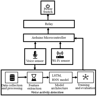
The proposed system uses audio signals to control an electrical power switch and is based on the architecture presented in Figure 1, showing the basic functionalities. A voice recorder is used to link the microcontroller and boost the level of the user’s audio, while a voice sensor is used to connect a relay and the power switch to read the pre-registered, pre-trained, and verified voice command. Recurrent Neural Networks (RNNs) with Long Short-Term Memory (LSTM) networks-based user's voice recognition was performed. LSTMs were used because they can effectively capture temporal dependencies in sequential data typical of audio signals.
Figure 1. The architecture of the proposed system.
2.1. RNN and LSTM Voice Activity Detection (VAD)
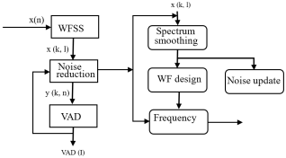
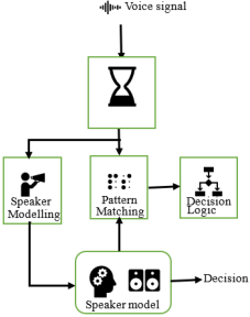
A typical voice activity detection structure shown in Figure 2, is supported by RNNs and LSTMs, and commences with the voice capturing using the voice sensor. The voice recording is followed by a Wiener filtering spectral subtraction (WFSS) denoising process depicted in Figure 3.
Figure 2. Voice activity detection.
Figure 3. The denoising process.
The mining of the Mel-frequency cepstral coefficients (MFCCs) or other relevant structures from the filtered audio signal follows, while the obtained data is segregated into training and testing sets. Obtaining the MFCCs from the audio comprises the partitioning of the audio into short segments, derivation of the power spectrum of every segment, subjecting the power spectra to a Mel filter bank, addition of the energy for each filter, derivation of the logarithm of the filter bank energies, estimation of the DCT of the logarithms, and obtaining the coefficients for each segment. Derivation of the MFCCs and the spectrogram based on Short-Time Fourier Transform (STFT), followed sequentially by the segmentation of the signal into segments of fixed length. Next is the application of a window with some overlap. The spectrogram represents the squared magnitude of the STFT. The STFT of the signal is x(n), w(n) is the window and S(τ,k) is the spectrogram. The spectrum is mined as pieces of the spectrogram through Equation (1) :
X(τ,k) = STFT{x(n)}=N=0N-1xnwn-τe-jnk(1)
Sτ,k=Xτ,k2(2)
If D is the entire dataset comprising N samples, then D can be deduced from:
D=x1,y1x2,y2xNyN(3)
xi represents the input features while yi gives the associated label. A split on the dataset is the ratio α where 0<α <1. Typically, α is preset to 0.8, implying 80% of the data is engaged for training and 20% for testing. The number of training trials is Ntrain=αN and the number of testing samples is represented by Ntest=N-Ntrain. The dataset D is labeled to ensure that both the training and testing sets are not only holistic but also bias-free. Subsequently, the training set Dtrain and testing set Dtest are expressed by taking the leading Ntrain samples and the post-shuffling remaining Ntest samples, as presented in Equations (4) and (5), respectively.
Dtrain = (xπ1,yπ1)(xπ2,yπ2)(xπNtrainyπNtrain)(4)
Dtest = (xπNtrain+1,yπNtrain+1)(xπNtrain+2,yπNtrain+2)(xπN,yπN)(5)
The filtering operation entails spectrum leveling, noise approximation, and use of the Wiener filter as shown in Figure 3. The spectrum smoothing is premised on the average mean of the power spectrum over two successive frames and two spectral groups, while noise estimation is by updating the noise spectrum Ne(k) based on a first-order IIR filter that uses the smoothed spectrum Ysk, l. Ne(k) is derived from:
Ne(k) = λNe(k) + 1 - λYsk, l(6)
To design a Wiener filter (WF), the fresh signal S(k) is calculated from the spectral difference:
Sk, l= XβSl k, l+ 1-maxYsk, l-Nek, 0(7)
The Wiener filter H(k) is consequently obtained from:
ηk, l= max Sk,lNek, ηmin (8)
Hk, l=ηk,l1+ηk,l(9)
ηmin represents the default that is used to set the filter to a maximum attenuation and Si(k, l). The default is assumed to be zero at the beginning of the process. it is derived from:
Si(k, l) = max [Y (k, l)H(k, l), 16](10)
H(k, l) filter is flattened to do away with speedy changes across the co-existing frequencies that may seldomly cause noise.
2.2. Recurrent Neural Network
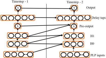
RNNs represent models that perform computation on data sequences. In the same manner as feed-forward neural networks (FF-NNs) that model displaceable functions over Rm  Rn, an RNN’s calculation is considered as nodes, each of which assesses an unassuming function to map its input values to a single scalar yield. FF-NN architecture with recurrence joined at several nodes is presented in Figure 4. Contrary to NNs, RNN nodes can accept input from nodes at preceding time stages, which enables the storage and manipulation of state as they repeatedly process a series of inputs and obtain several outputs. Rather than the commonly known weighted sum and non-linear activation of a multi-layer perceptron (MLP), the RNN nodes derive the quadratic equation of their inputs. The optional non-linearity is then carried out based on the formula:
V(x) = f(xTWQx +wLT+ wB)(11)
A node obtains its yield value V(x) from the vector x of its inputs based on Equation (11); WQ represents the upper-triangular scant matrix which has weights for quadratic terms, wL gives a vector of direct weights that resembles those in MLPs, and wB stands for a scalar bias. This approach is premised on the fact that higher-order Taylor polynomials do effectively round functions, and the products can be computed in a way similar to the Multiplicative RNNs. Nodes can equally evaluate the multidimensional Gaussian density (and other radial basis functions), noting that N(x; μ,Σ) can be written as e (-xTΣ-1+ 2μTΣ-1- μTΣ-1μ+ ln(z)). z is the Gaussian normalization constant .
2.3. Long-Short Term Memory (LSTM)
The LSTM is another version of RNN, which analyzes short and long-term data. It is formulated based on multiple cells with each having three essential parts that are saddled with the task of updating, recalling, and discarding information . The LSTM modules are autonomous and engage a sigmoid "forget gate", ft to determine if any information needs to be excluded or removed from the ct - 1cell. The gate generates multiple numbers in the range of 0 and 1 for each of the components in ct - 1after reading the values ht - 1and xt. The forget gate and the element-wise sum function for the gate are presented in Equation (12) and Equation (13), respectively.
ft = σ (Wf. [ht-1,  xt] + bf(12)
it= σ (Wi. [ht-1,  xt] + bi(13)
Ct̂= tanh (Wc. [ht-1, xt] + bC(14)
Figure 4. Feed-forward NN architecture with recurrence added at various nodes.
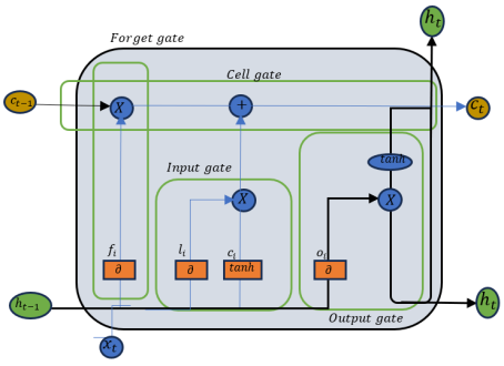
The final part of the LSTM is the output gate, which represents the neuron layer with the sigmoid activation function at the far right of the neuron layer line . Its output contributes nothing to the value of the cell, though the gate is needed for differentiating the cell state from the actual output . LSTM is computed based on the formula:
ot = σ (Wo. [ht-1, xt] + bo(15)
ht = ot. tanh (Ct)(16)
Figure 5. The architecture for the LSTM.
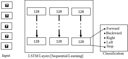
Figure 6. LSTM speech recognition architecture.
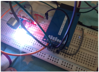
Figure 5 presents the operational flow of the LSTM neural network engaged for the knowledge and classification of the sequence. Its voice recognition component is presented in Figure 6, showing the leftmost section with a sequence of input data frames that indicate a time series of data, images, audio, or any sequential data for the LSTM network processing. The central section contains several LSTM layers. Each of the layers has 128 units or neurons, which are designed to process the input data in serial order and capture the long and short-term dependencies in the sequence. The links that connect the layers provide the movement of information across the network, such that every layer passes treated information to the succeeding layer. The rightmost section gives the classification output of the LSTM network. The processed data from the final LSTM layer is fed into a classification mechanism that assigns one of the five possible classes, namely Forward, Backward, Right, Left, and Stop. Each class is represented by a blue dot, indicating the possible actions or outcomes that the model could predict.
A dropout layer is added between LSTM layers to guard against overfitting. The dropout layer arbitrarily sets a segment of input units to 0 at every update while performing training. This ensures the avoidance of overfitting and, in no specific order, sets a fraction of input units to zero at every training time update. Dropout is a normalization method that randomly assigns a fraction of input units to zero during training to avoid overfitting. During training, each neuron's output is assigned zero and a probability p (dropout rate) that the other neurons' outputs are standardized with 1 1 - p to retain the anticipated sum of inputs constant. If x is the input vector to the dropout layer and p is the dropout rate (probability of dropping a neuron), then ri is the Bernoulli random variable that is 1 with probability 1−p and 0 with probability p, then the output, yi is derived from:
yi=rixi1-p(17)
ri Bernoulli(1-p).
A dense layer is used to determine the learned sequence patterns and the ultimate classification with the ReLU activation function. The output layer shows a single neuron with a sigmoid activation function for binary classification (speech or non-speech). Given that h is the input to the dense layer, W is the weight matrix of the shape (n,m), b is the bias vector of the shape (m) and ϕ is an activation function, then the output y of the dense layer is computed based on the formula :
y=ϕ(Wh+b)(18)
n is the sum of input units and m is the number of output units. The model training encompasses the minimization of the loss function by keeping the model parameters (weights and biases) up-to-date using an optimization algorithm that involves a forward pass and loss calculation. The predicted output y is derived using the current parameters of the model in the forward pass as follows:
y= f(X,w)(19)
X represents the input data, and w stands for the model constraints. While calculating the loss, the model is trained to distinguish between speech and speech-free activities, while binary cross-entropy is engaged for the measurement of the performance of the classification model, which gives a probability value in the range 0 and 1, and it is calculated from:
L=-1N i=1Nyilogpi+1-yilog(1-pi)(20)
N is the number of samples, yi is the true label of the ith sample (0 or 1), pi is the predicted probability that the ith sample belongs to the positive class (output of the sigmoid activation function) . Following this operation is the backward pass and parameter update. In the backward pass, the gradients of the loss function regarding the model parameters, wLw is derived. The model parameters are updated using the Adam optimizer rules presented thus:
mt= β1mt-1+1-β1wLw(21)
vt= β2vt-1+(1- β2)(wLw)2(22)
mt̂= mt1- β1t(23)
vt̂= vt1- β2t(24)
w w- ηvt̂+ ϵ.mt̂(25)
mt and vt represent the first and second-moment estimates, respectively, β1and β2 are decay rates, typically set to 0.9 and 0.999, respectively, and mt ̂and vt̂ are bias-corrected estimates .
3. Experimental Study
The hardware setup for the experimental study includes an ESP32-S3 development board, an external KY-037 microphone module with an operating voltage of 3.3V-5V, a relay module, a 2N222 transistor, resistors, an SD card module, a light bulb, a 3.3V regulated power supply, a breadboard, jumper wires, and a computer system. The ESP32-S3 development board is the core hardware and comprises a dual-core microcontroller with integrated AI acceleration, making it suitable for running lightweight machine learning models and handling real-time audio signal processing. It serves as the platform for code execution, model deployment, and hardware interfacing. A microphone module has analog, ground, voltage, and digital pins and was used to capture the user’s voice commands with an operating voltage of 3.3V-5V. It was connected to the ESP32-S3 through the analog input pin. The relay module serves as a switching device that allows the ESP32-S3 to effectively control and achieve the low voltage requirement of the light bulb, which demonstrates the switching functionality after activating or deactivating based on recognized commands. The 3.3V regulated power supply is crucial for the reliable operation of both the microcontroller and peripheral components. During prototyping, the breadboard and jumper wires allowed easy circuit assembly and testing, as well as modifying and troubleshooting of the hardware connections.
The software tools for the experimental study include Arduino Integrated Development Enterprise (AIDE), ESP32 Board Support Package (EBSP), Digital Signal Processing (DSP)/MFCC Extraction Libraries, Serial Communication Tools, and Microsoft Windows 10 Operating System. The AIDE is the primary development environment used for writing, compiling, and uploading code to the ESP32-S3 board. It provides a simple and user-friendly interface, along with debugging tools such as the Serial Monitor and Plotter, which are essential for monitoring microphone signals and system behavior. The EBSP was installed within the AIDE to aid compatibility with the ESP32-S3 microcontroller and provide necessary drivers, libraries, and core functionalities that allow seamless interaction and communication between the AIDE and ESP32 hardware. The DSP’s ArduinoFFT and custom MFCC extraction code libraries were responsible for converting raw microphone signals into MFCCs that serve as the matching features during the preprocessing at the model training phase. Serial communication tools such as the Arduino Serial Monitor or external terminal applications were used for debugging and displaying output messages, monitoring recognition results, and tracking errors during system development and testing. A Pentium IV HP laptop PC system 11th Gen Intel Core (TM) i5-1135G7, which runs at 2.40GHz with RAM size 16.0GB and SSD storage of 240GB in the Windows 7 operating system environment, was used to facilitate installation and use of the software tools.
The major purpose of the implementation phase is to convert the system design into source code. Each component of the design is implemented as a program module. The end product of this phase is a module that collaborates with other modules to achieve the objectives and ensure correctness and overall synergy.
The microcontroller ESP32S3 board shown in Figure 7 served as the heart of the setup. It was connected to an external microphone, which acts as a voice sensor. The analog pin of the microphone was connected to its equivalent pin on the board, and the Voltage at the Common Collector (VCC) pin was connected to the 3.3V breadboard. The ground pin was used to achieve the earth circuit required for system stability and safety. A relay module was connected to the ESP32S3 to control the light bulb, while the SD card module was connected to the breadboard and the ESP32S3 using jumper wires (male-to-male, female-to-male, female-to-female), which makes it easy to test, modify, and troubleshoot.
Figure 7. The ESP32S3 Board Setup.
3.1. Voice Control
The voice control section of the setup enables response to spoken commands by converting spoken speech into digital features that are compared and interpreted by the microcontroller. Voice characteristics and spoken keywords were used to control the ESP32-S3 microcontroller-based electrical device. The voice control was divided into speaker verification and command recognition. When the system is powered on, the ESP32-S3 continuously listens for speech input through an external microphone, which converts the user’s voice into an analog electrical signal, which is then sampled by the ESP32-S3’s analog-to-digital converter (ADC) at a sampling rate of 8 kHz. The digitization process transforms the spoken voice into a sequence of digital samples that can be processed by the system. The captured audio signal undergoes pre-processing through the removal of silence segments, amplitude normalization, signal framing into short segments, and application of a Hamming window to each frame for achieving voice templates and incoming speech uniformity. The preprocessing was followed by the extraction of MFCC from the speech signal to closely represent human auditory perception and provide compact and discriminative speech features. The MFCC extraction involves transformation of speech frames to the frequency domain, logarithmic compression of spectral energy, and conversion to cepstral coefficients. The resulting MFCC feature vectors represent the unique characteristics of the speaker’s voice and the spoken command.
At the speaker verification stage, the extracted MFCC features are compared with stored speaker templates using Dynamic Time Warping (DTW), which aligns two speech sequences of different lengths and calculates the minimum distance between them. If the computed DTW distance is below a predefined threshold, the speaker is considered authorized. This step ensures that only registered users can control the system. Once the speaker is successfully verified, the system listens for a command word, which is again converted into MFCC features and compared with stored command templates for “ON” and “OFF” using DTW. The command corresponding to the lowest DTW distance is selected as the recognized command. After command recognition, if the command is ‘ON’, the ESP32-S3 activates the relay and turns the connected device on. If the command is ‘OFF’, the relay is deactivated, and the device is turned off. The ON/Off control demonstrates real-time voice-based control of an electrical device. After executing the command, the system clears temporary buffers and returns to the listening state, ready to process the next voice input, which allows continuous and hands-free operation.
3.2. Experimental Results
Voices from 30 randomly selected individuals were used for the evaluation of the system. Each individual provided three predefined speaker verification phrases for each of the ON and OFF commands. From the collected commands, the MFCC template set {ON, OFF} was generated and stored for each of the selected individuals. Minimal-size templates were used to reduce memory consumption and intra-speaker variation. The study is based on the configuration presented in Table 1.
Table 1. Experimental configurations.

Parameter

Value

Number of participants

30

Voice repetitions per participant

6 (3 ON, 3 OFF)

Stored templates per participant

2 (1 ON, 1 OFF)

Genuine verification attempts

180

Impostor verification attempts

180

Feature extraction method

MFCC

Matching algorithm

DTW

Microcontroller

ESP32-S3

3.3. Verification Testing Procedure
Speaker verification was evaluated using both genuine attempts and impostor attempts. In genuine attempts, authorized users speak the verification phrase, while impostor attempts are those in which unauthorized users attempt to speak the verification phrase. In genuine attempts, a participant’s voice sample was matched against his/her own template (P1 → T1, T2, T3) to measure the system’s ability to correctly accept authorized users. The key performance metric here is the False Rejection Rate (FRR), which quantifies how often the system incorrectly rejects genuine users. In the impostor attempts, a participant’s voice sample was matched against other participants’ templates (P1 → T4, T5, T6, …, T90). These trials measured the system’s ability to correctly reject unauthorized users. The key performance metric here is the False Acceptance Rate (FAR), which quantifies how often the system incorrectly accepts impostors. The verification results showed that the system achieved a balance between FRR and FAR, demonstrating its effectiveness in distinguishing between genuine and impostor speakers. This evaluation highlights the security aspect of the system, ensuring that only enrolled users can successfully issue commands. The genuine attempt results for ON and OFF commands are presented in Tables 2 and 3, respectively, while the impostor's attempt results for ON and OFF commands are presented in Tables 4 and 5, respectively. The experimentally obtained FAR and FRR are presented in Table 6.
Table 2. Genuine Attempt Results for ON command (FRR Evaluation).

Participant ID

Total Genuine Attempts

Correctly Accepted

Falsely Rejected

FRR (%)

P1

3

3

0

0

P2

3

2

1

33.3

P3

3

3

0

0

P4

3

3

0

0

P5

3

3

0

0

P6

3

3

0

0

P7

3

3

0

0

P8

3

3

0

0

P9

3

3

0

0

P10

3

3

0

0

P11

3

3

0

0

P12

3

3

0

0

P13

3

3

0

0

P14

3

3

0

0

P15

3

3

0

0

P16

3

3

0

0

P17

3

3

0

0

P18

3

3

0

0

P19

3

3

0

0

P20

3

3

0

0

P21

3

3

0

0

P22

3

1

2

66.7

P23

3

1

2

66.7

P24

3

2

1

33.3

P25

3

3

0

0

P26

3

3

0

0

P27

3

3

0

0

P28

3

2

1

33.3

P29

3

2

1

33.3

P30

3

2

1

33.3

Total

90

81

9

10

Table 3. Genuine Attempt Results for OFF command (FRR Evaluation).

Participant ID

Total Genuine Attempts

Correctly Accepted

Falsely Rejected

FRR (%)

P1

3

3

0

0

P2

3

3

0

0

P3

3

3

0

0

P4

3

3

0

0

P5

3

3

0

0

P6

3

3

0

0

P7

3

3

0

0

P8

3

3

0

0

P9

3

1

2

66.7

P10

3

3

0

0

P11

3

3

0

0

P12

3

3

0

0

P13

3

3

0

0

P14

3

3

0

0

P15

3

3

0

0

P16

3

1

2

66.7

P17

3

3

0

0

P18

3

3

0

0

P19

3

3

0

0

P20

3

3

0

0

P21

3

3

0

0

P22

3

2

1

33.3

P23

3

2

1

33.3

P24

3

2

1

33.3

P25

3

3

0

0

P26

3

3

0

0

P27

3

3

0

0

P28

3

2

1

33.3

P29

3

2

1

33.3

P30

3

2

1

33.3

Total

90

80

10

11.1

Table 4. Impostor Attempt Results for ON command (FAR Evaluation).

Participant ID

Total Impostor Attempts

Correctly Rejected

Falsely Accepted

FAR (%)

P1

3

3

0

0

P2

3

2

1

33.3

P3

3

3

0

0

P4

3

1

2

66.7

P5

3

3

0

0

P6

3

3

0

0

P7

3

3

0

0

P8

3

3

0

0

P9

3

3

0

0

P10

3

3

0

0

P11

3

3

0

0

P12

3

3

0

0

P13

3

3

0

0

P14

3

3

0

0

P15

3

3

0

0

P16

3

3

0

0

P17

3

3

0

0

P18

3

3

0

0

P19

3

3

0

0

P20

3

3

0

0

P21

3

3

0

0

P22

3

3

0

0

P23

3

3

0

0

P24

3

3

0

0

P25

3

3

0

0

P26

3

3

0

0

P27

3

3

0

0

P28

3

3

0

0

P29

3

3

0

0

P30

3

3

0

0

Total

90

87

3

33.3

Table 5. Impostor Attempt Results for OFF command (FAR Evaluation).

Participant ID

Total Impostor Attempts

Correctly Rejected

Falsely Accepted

FAR (%)

P1

3

3

0

0

P2

3

2

0

0

P3

3

3

0

0

P4

3

1

1

33.3

P5

3

3

0

0

P6

3

3

0

0

P7

3

3

0

0

P8

3

3

0

0

P9

3

3

1

33.3

P10

3

3

0

0

P11

3

3

0

0

P12

3

3

0

0

P13

3

3

0

0

P14

3

3

0

0

P15

3

3

0

0

P16

3

3

0

0

P17

3

3

0

0

P18

3

3

0

0

P19

3

3

0

0

P20

3

3

0

0

P21

3

3

0

0

P22

3

3

0

0

P23

3

3

0

0

P24

3

3

0

0

P25

3

3

0

0

P26

3

3

0

0

P27

3

3

0

0

P28

3

3

0

0

P29

3

3

0

0

P30

3

3

0

0

Total

90

88

2

2.2

Table 6. The obtained FAR and FRR values.

Metric

Formula

Value (%)

FRR

(False Rejections ÷ Genuine Attempts) × 100

10.6

FAR

(False Acceptances ÷ Impostor Attempts) × 100

2.8

3.4. Command Recognition Performance
Command recognition refers to the system’s ability to correctly classify the spoken command as either ON or OFF, independent of the speaker’s identity. Every utterance, whether genuine or impostor, contained one of these two commands, and the system had to decide which command was spoken. The recognition process involved comparing the input features against the stored ON and OFF templates and selecting the closest match. Performance was evaluated using the confusion matrix shown in Table 7, which recorded how many ON commands were correctly recognized and how many were misclassified as OFF, and vice versa. From the confusion matrix, per-command accuracies were computed and presented in Table 8. The ON commands achieved an accuracy of approximately 91%, while the OFF commands achieved 88.9% accuracy, resulting in an overall command recognition accuracy of 90%. The evaluation highlights the usability aspect of the system, ensuring that once a speaker is verified, the intended command is correctly understood and executed. The system’s overall error and accuracy ratings are presented in Table 9.
Table 7. Confusion Matrix (180 Genuine Attempts).

Predicted ON

Predicted OFF

Actual ON (90)

82

8

Actual OFF (90)

10

80

Table 8. Command Recognition Performance (ON/OFF).

Command

Total Genuine Attempts

Correctly Recognized (True Positives)

Misrecognized (False Negatives/Positives)

Accuracy (%)

ON

90

82 (Actual ON → Predicted ON)

8 (Actual ON → Predicted OFF)

91.1

OFF

90

80 (Actual OFF → Predicted OFF)

10 (Actual OFF → Predicted ON)

88.9

Total

180

162

18

90.00

Table 9. Overall System Performance Summary.

Metric

Value (%)

False Rejection Rate (FRR)

10.60

False Acceptance Rate (FAR)

2.800

Command Recognition Accuracy (CRA)

90.00

4. Conclusion
The paper presents the design and implementation of a voice-based framework for remote control of power switches. The framework will be suitable for contactless operation of power switches and ultimately eliminate the event of accidental switch activation, increase security, protect against unauthorized users, and enable individuals with physical disabilities to effortlessly operate electrical and power switches. The implementation hardware includes an ESP32-S3 development board, an external KY-037 microphone module with an operating voltage of 3.3V-5V, a relay module, a 2N222 transistor, resistors, an SD card module, a light bulb, a 3.3V regulated power supply, a breadboard, jumper wires, and a computer system. A combination of Arduino Integrated Development Enterprise (AIDE), ESP32 Board Support Package (EBSP), Digital Signal Processing (DSP)/MFCC Extraction Libraries, Serial Communication Tools, and Microsoft Windows 10 Operating System also provided the software support. The implementation based on multiple voice commands from thirty randomly selected individuals established the ability of the system to correctly classify the spoken command as either ON or OFF, independent of the speaker’s identity, based on comparison of the input reference and template ON/OFF features. Performance evaluation based on the confusion matrix established that a very high percentage of the ON and OFF commands were correctly recognized with an accuracy of approximately 91% and 89%, respectively, resulting in an overall command recognition accuracy of 90%. The evaluation metrics highlight the high usability of the system and its ability to effectively verify users and operate as intended.
Abbreviations

RNN

Recurrent Neural Networks

LSTM

Long Short-Term Memory

DSP

Digital Signal Processing

AM

Amplitude Modulation

FM

Frequency Modulation

PSK

Phase Shift Keying (PSK)

QAM

Quadrature Amplitude Modulation

FT

Fourier Transform

STFT

Short-Time Fourier Transform

LPC

Linear Predictive Coding

HMM

Hidden Markov Models

VoIP

Voice Over Internet Protocol

AI

Artificial Intelligence

NLU

Natural Language Understanding

VAD

Voice Activity Detection

MFCC

Mel-frequency Cepstral Coefficients

WF

Wiener Filter

FF-NN

Feed-forward Neural Networks

MLP

Multi-Layer Perceptron

AIDE

Arduino Integrated Development

EBSP

Enterprise ESP32 Board Support Package

ADC

Analog-to-Digital Converter

DTW

Dynamic Time Warping

FRR

False Rejection Rate

FAR

False Acceptance Rate

Acknowledgments
The noble role played by the Federal University of Technology, Akure, Nigeria’s Centre for Research and Development (CERAD), towards the success of this research is greatly acknowledged.
Author Contributions
Gabriel Babatunde Iwasokun: Conceptualization, Supervision, Data Curation, Formal Analysis, Funding Acquisition, Investigation, Writing – original draft, Writing – review & editing
Dayo Olufunso Alowolodu: Conceptualization, Data Curation, Formal Analysis, Investigation, Writing – original draft, Writing – review & editing
Raphael Olufemi Akinyede: Conceptualization, Data Curation, Formal Analysis, Funding Acquisition, Investigation, Writing – original draft, Writing – review & editing
Blossom Oluwakorede Remi-Ofakunrin: Conceptualization, Data Curation, Formal Analysis
Michael Abejide Adegoke: Conceptualization, Data Curation, Writing – original draft, Writing – review & editing
Bidemi Tosin Ashade: Methodology, Resources, Validation, Visualization
Oyinkansola Anuoluwapo Olagunju: Methodology, Resources, Validation, Visualization
Oluwatobi Adedayo Balogun: Methodology, Resources, Validation, Visualization
Michael Tokunbo Adenibuyan: Methodology, Resources, Validation, Visualization
Johnson Adeleke Adeyiga: Methodology, Resources, Validation, Visualization
Adebisi Esther Oluwatosin: Methodology, Resources, Validation, Visualization
Moses Joy Achas: Methodology, Resources, Validation, Visualization
Funding
This research is funded by the Nigerian government’s 2023 Research Grant through the National Tertiary Education Trust Fund (TETFund).
Conflicts of Interest
The authors declare that there are no conflicts of interest.
References
[1] Abe B. C., Araromi H. O., Shokenu E. S., Idowu P. O., Babatunde J. D., Adeagbo M. O., Itanrin H. O. (2022), Biometric Access Control Using Voice and Fingerprint, Engineering and Technology Journal, 7(7), Available:
[2] Rabiner L. and Juang B. (2019), Fundamentals of Speech Recognition, New Jersey: Prentice-Hall Inc., 2019.
[3] Srivastava N., Hinton G., Krizhevsky A., Sutskever I., and Salakhutdinov R. (2014), Dropout: A Simple Way to Prevent Neural Networks from Overfitting, Journal of Machine Learning Research 15 (2014) 1929-1958. Available:
[4] Rabiner L. R. and Schafer R. W. (2011). Theory and Applications of Digital Speech Processing, Available:
[5] Tan K., and Wang D. (2018). A Convolutional Recurrent Neural Network for Real-Time Speech Enhancement. Interspeech. Available:
[6] Oord A., Dieleman S., Zen H., Simonyan K., Vinyals O., Graves A., Kalchbrenner N., Senior A., and Kavukcuoglu K. (2016). Wavenet: A Generative Model for Raw Audio
[7] Yang C. H., Gu Y., Liu Y. C., Ghosh S., Bulyko I., Stolcke A. (2023), Generative speech recognition error correction with large language models and task-activating prompting, in: 2023 IEEE Automatic Speech Recognition and Understanding Workshop (ASRU), IEEE, 1-8. Available:
[8] Maral F., Hamidreza R., Nassim R., and Hamed A. (2023). Ultra-Low-Power Voice Activity Detection System Using Level-Crossing Sampling, Electronics, 12(4): 795. Available:
[9] Amannah C. I. and Nlerum P. (2022). Voice-Based Automation Control Platform for Home Electrical Devices, Available:
[10] Junji A., Satoshi A., Takahiro Y., and Kenichi K. (2022). Voice Control Device and Voice Control System.
[11] Iliev, Y., and Ilieva, G. (2023). A Framework for Smart Home System with Voice Control Using NLP Methods. Electronics, 12(1), 116.
[12] Samia D. S. M., Bessa E., Blumstein D. T., Nunes J. A. C. C., Azzurro E., Morroni L., Sbragaglia V., Januchowski-Hartley F. A., and Geffroy B. (2019). A Meta-Analysis of Fish Behavioural Reaction to Underwater Human Presence. Fish and Fisheries, 20, 817-829. Available:
[13] Thad H. and Keir M. (2013), Recurrent Neural Networks for Voice Activity Detection, ICASSP 2013, static.googleusercontent.com
[14] Hajiaghayi M., Vahedi E. (2019). Code Failure Prediction and Pattern Extraction Using LSTM Networks. 55-62.
[15] Graves A., Mohamed A. R., and Hinton, G. (2013), Speech Recognition with Deep Recurrent Neural Networks. 2013, Available:
[16] Wanzala J. N. and Atim M. R. (2024), Design and simulation of a smart master switch system based on multi-input XOR logic gate, Discover Electronics, 1: 23. Available:
[17] Wang Z., Defang L., Yunan S., Xiaoyi P., Feng L., John C. S. L., and Kui R. (2022), A Survey on IoT-Enabled Home Automation Systems: Attacks and Defenses, IEEE Communications Surveys and Tutorials, 24(4). Available: chrome-extension:
[18] Sakshi S., Manish K. M., Nisha D. (2023), Home Automation System, International Journal of Novel Research and Development, 8(1); 96-100. Available:
[19] Bansal, G. and Yadav, D. (2021), Developing a multidimensional scale for measuring social media habit: A nomological examination in the context of cyberbullying. In the proceedings of the 27th Americas Conference on Information Systems (AMCIS). Available:
[20] Bensimon, M., Greenberg, S., and Haiut, M. (2021). Using a Low-Power Spiking Continuous Time Neuron (SCTN) for Sound Signal Processing. Sensors, 21(4), 1065.
[21] Ahmad A., Mansoor A., Abid K. (2021). Audit Logs Management and Security - A Survey, Kuwait Journal of Science, Vol. 48 (3), 1-18,
Cite This Article
  • APA Style

    Iwasokun, G. B., Alowolodu, D. O., Akinyede, R. O., Remi-Ofakunrin, B. O., Adegoke, M. A., et al. (2026). RNN, LSTM, and Voice Signal Model for Electrical Switch Regulator. Science Journal of Circuits, Systems and Signal Processing, 13(2), 20-32. https://doi.org/10.11648/j.cssp.20261302.11

    Copy | Download

    ACS Style

    Iwasokun, G. B.; Alowolodu, D. O.; Akinyede, R. O.; Remi-Ofakunrin, B. O.; Adegoke, M. A., et al. RNN, LSTM, and Voice Signal Model for Electrical Switch Regulator. Sci. J. Circuits Syst. Signal Process. 2026, 13(2), 20-32. doi: 10.11648/j.cssp.20261302.11

    Copy | Download

    AMA Style

    Iwasokun GB, Alowolodu DO, Akinyede RO, Remi-Ofakunrin BO, Adegoke MA, et al. RNN, LSTM, and Voice Signal Model for Electrical Switch Regulator. Sci J Circuits Syst Signal Process. 2026;13(2):20-32. doi: 10.11648/j.cssp.20261302.11

    Copy | Download

  • @article{10.11648/j.cssp.20261302.11,
      author = {Gabriel Babatunde Iwasokun and Dayo Olufunso Alowolodu and Raphael Olufemi Akinyede and Blossom Oluwakorede Remi-Ofakunrin and Michael Abejide Adegoke and Bidemi Tosin Ashade and Oyinkansola Anuoluwapo Olagunju and Oluwatobi Adedayo Balogun and Michael Tokunbo Adenibuyan and Johnson Adeleke Adeyiga and Adebisi Esther Oluwatosin and Moses Joy Achas},
      title = {RNN, LSTM, and Voice Signal Model for Electrical Switch Regulator},
      journal = {Science Journal of Circuits, Systems and Signal Processing},
      volume = {13},
      number = {2},
      pages = {20-32},
      doi = {10.11648/j.cssp.20261302.11},
      url = {https://doi.org/10.11648/j.cssp.20261302.11},
      eprint = {https://article.sciencepublishinggroup.com/pdf/10.11648.j.cssp.20261302.11},
      abstract = {The creation of platforms for systematic control of electric power switches based on the hands-on application of Artificial Intelligence in day-to-day life lessens the prospect of unintended switch initiation. It can enhance security by ensuring that only authorized users receive responses. Physically challenged individuals also need systems bereft of point-point contacts or interactions with electrical or power switches. Some of the known methods for achieving these objectives include smart objects, the Internet of Things, and biometric technologies, each with its strengths and weaknesses. This paper proposed a voice signal model for remote control of electrical switches. The model uses a voice recorder connected to an Arduino microcontroller to boost the audio or voice signal from the user, while a voice sensor is also linked to a power switch relay to acquire the voice signal for registration, training, verification, and processing. The Arduino microcontroller sensor runs TinyML and TensorFlow Lite environment sensors while operating at an adjustable voltage. A switch relay was required for limiting the voltage to a required level based on synergy with the Arduino microcontrollers. A Wi-Fi module was also used for launching the microcontroller and the TCP/IP connections based on Hayes-style commands. The system runs with an electromechanical device designed for the flow of electric current to open or close the electrical circuit. The user voice recognition leverages Recurrent Neural Networks (RNNs) and Long Short-Term Memory (LSTM) networks to guarantee effective capturing of temporal dependencies in sequential data typical of audio signals. The implementation of the framework on specialized hardware and software has established its ability to effectively classify spoken commands as either ON or OFF independent of the speaker’s identity, based on comparison of the input features. Performance evaluation based on the confusion matrix established that a very high percentage of the input commands were correctly recognized with an accuracy of 90%.},
     year = {2026}
    }
    

    Copy | Download

  • TY  - JOUR
    T1  - RNN, LSTM, and Voice Signal Model for Electrical Switch Regulator
    AU  - Gabriel Babatunde Iwasokun
    AU  - Dayo Olufunso Alowolodu
    AU  - Raphael Olufemi Akinyede
    AU  - Blossom Oluwakorede Remi-Ofakunrin
    AU  - Michael Abejide Adegoke
    AU  - Bidemi Tosin Ashade
    AU  - Oyinkansola Anuoluwapo Olagunju
    AU  - Oluwatobi Adedayo Balogun
    AU  - Michael Tokunbo Adenibuyan
    AU  - Johnson Adeleke Adeyiga
    AU  - Adebisi Esther Oluwatosin
    AU  - Moses Joy Achas
    Y1  - 2026/07/27
    PY  - 2026
    N1  - https://doi.org/10.11648/j.cssp.20261302.11
    DO  - 10.11648/j.cssp.20261302.11
    T2  - Science Journal of Circuits, Systems and Signal Processing
    JF  - Science Journal of Circuits, Systems and Signal Processing
    JO  - Science Journal of Circuits, Systems and Signal Processing
    SP  - 20
    EP  - 32
    PB  - Science Publishing Group
    SN  - 2326-9073
    UR  - https://doi.org/10.11648/j.cssp.20261302.11
    AB  - The creation of platforms for systematic control of electric power switches based on the hands-on application of Artificial Intelligence in day-to-day life lessens the prospect of unintended switch initiation. It can enhance security by ensuring that only authorized users receive responses. Physically challenged individuals also need systems bereft of point-point contacts or interactions with electrical or power switches. Some of the known methods for achieving these objectives include smart objects, the Internet of Things, and biometric technologies, each with its strengths and weaknesses. This paper proposed a voice signal model for remote control of electrical switches. The model uses a voice recorder connected to an Arduino microcontroller to boost the audio or voice signal from the user, while a voice sensor is also linked to a power switch relay to acquire the voice signal for registration, training, verification, and processing. The Arduino microcontroller sensor runs TinyML and TensorFlow Lite environment sensors while operating at an adjustable voltage. A switch relay was required for limiting the voltage to a required level based on synergy with the Arduino microcontrollers. A Wi-Fi module was also used for launching the microcontroller and the TCP/IP connections based on Hayes-style commands. The system runs with an electromechanical device designed for the flow of electric current to open or close the electrical circuit. The user voice recognition leverages Recurrent Neural Networks (RNNs) and Long Short-Term Memory (LSTM) networks to guarantee effective capturing of temporal dependencies in sequential data typical of audio signals. The implementation of the framework on specialized hardware and software has established its ability to effectively classify spoken commands as either ON or OFF independent of the speaker’s identity, based on comparison of the input features. Performance evaluation based on the confusion matrix established that a very high percentage of the input commands were correctly recognized with an accuracy of 90%.
    VL  - 13
    IS  - 2
    ER  - 

    Copy | Download

Author Information