Abstract
This study presents the design and performance analysis of a cascade refrigeration system aimed at achieving ultra-low temperatures of -80°C, essential for vaccine storage and cryogenic applications. Cascade refrigeration systems are widely used for such applications because they reduce compressor work and improve overall efficiency compared to single-stage systems, particularly when a large temperature lift is required. The system analyzed in this study utilizes R-134a in the upper-temperature circuit and investigates the performance of four candidate refrigerants — R-13, R-23, R-170, and R-290 — in the lower-temperature circuit. Thermodynamic simulations were conducted using Engineering Equation Solver (EES) to determine the coefficient of performance (COP) of each circuit and the overall system, along with the corresponding refrigerant mass flow rates, under a fixed set of operating conditions. The results show that R-23 yields the highest overall COP of 1.816, outperforming R-13 (1.538), R-170 (1.704), and R-290 (1.695), owing to its superior lower-circuit COP of 5.758. A parametric study further examined the effect of evaporator temperature and ambient temperature on system performance, showing that overall COP declines as the evaporator temperature is lowered from -20°C to -50°C, while the lower-circuit COP improves over the same range. Heat transfer analysis highlights the significance of insulation properties, with an estimated cooling load of 72 kW for a 1 m³ chamber at an ambient temperature of 40°C, based on a polyurethane foam insulation layer of 0.25 m thickness. The findings emphasize the critical role of refrigerant selection in enhancing efficiency and operational stability, contributing to sustainable and energy-efficient refrigeration solutions for ultra-low-temperature storage applications such as vaccine preservation.
Keywords
Cascade Refrigeration System, Cryogenic Applications, Refrigerant Selection, Thermodynamic Analysis,
Vaccine Storage Refrigeration
1. Introduction
The demand for ultra-low temperature refrigeration systems has increased significantly in recent years, driven by advancements in pharmaceuticals, cryogenic storage, and specialized industrial applications. In particular, the storage and preservation of vaccines and biological materials necessitate precise and stable low-temperature environments, often reaching -80°C or lower. Cascade refrigeration systems (CRS) present an effective solution for achieving such low temperatures by utilizing multiple refrigerant circuits operating at different temperature levels. This approach leverages the thermodynamic properties of specific refrigerants to progressively reduce the temperature, thereby mitigating the limitations encountered in single-stage systems
| [1] | A. Da Silva, E. P. Bandarra Filho, and A. H. P. Antunes, “Comparison of a R744 cascade refrigeration system with R404A and R22 conventional systems for supermarkets,” in Applied Thermal Engineering, Aug. 2012, pp. 30–35.
https://doi.org/10.1016/j.applthermaleng.2011.12.019 |
[1]
.
The inherent advantage of cascade systems lies in their ability to reduce compressor work and enhance system efficiency. By employing two separate refrigeration circuits interconnected via an intermediate heat exchanger, the system minimizes the temperature lift required across individual compressors
| [6] | Tan, H., Bai, M., Xu, L., Li, X., Liu, Z. Experimental study on the pull-down performance of a −80°C cascade refrigeration freezer. Asia-Pac. J. Chem. Eng. 2023, 18(3), e2888.
https://doi.org/10.1002/apj.2888 |
[6]
. This design not only improves the COP but also extends the operational lifespan of the equipment. Additionally, CRS configurations allow for greater flexibility in refrigerant selection, enabling the use of environmentally friendly and high-performing refrigerants tailored to the specific temperature requirements of each circuit
| [8] | Lee, S.-B., Shin, C.-H., Lee, J.-H. A Novel Approach of −80°C Cascade Refrigeration System Using Non-Flammable Quaternary Refrigerants for Semiconductor Process Applications. Energies 2024, 17(23), 6178. https://doi.org/10.3390/en17236178 |
| [9] | Kumar, S., Gahlot, P., Kumar, S. A novel ultra-low temperature cascade refrigeration with dual auxiliary loop to enhance thermal performance. Sci. Rep. 2025, 15, 23214.
https://doi.org/10.1038/s41598-025-08462-9 |
[8, 9]
.
However, the performance of cascade refrigeration systems is highly sensitive to the choice of refrigerants, operating conditions, and design parameters. A comprehensive thermodynamic analysis is essential to optimize these variables and ensure the system meets the desired low-temperature targets while maintaining energy efficiency. This report focuses on the design and performance analysis of a cascade refrigeration system with a target evaporator temperature of -80°C, a critical threshold for numerous medical and industrial applications. The study will explore different refrigerant combinations to identify the most effective configuration, with a particular focus on maximizing the overall COP and minimizing energy consumption.
The scope of this study encompasses the design and analysis of a two-stage cascade refrigeration system with an upper-temperature circuit utilizing R-134a refrigerant and a lower-temperature circuit employing different refrigerants, including R-13, R-23, R-170, and R-290. The system is designed to provide cooling for a chamber with an internal volume of 1 m³, simulating a typical vaccine storage unit.
The thermodynamic analysis will be conducted using Engineering Equation Solver (EES) software, allowing for the accurate simulation of refrigerant properties and cycle performance. Key performance metrics such as COP, mass flow rates, and heat exchanger capacities will be evaluated and compared across different operating conditions. The study also includes the calculation of cooling loads based on heat transfer through the insulated chamber walls, considering an ambient temperature of 40°C and an internal temperature of -80°C.
1.1. Cascade System Overview
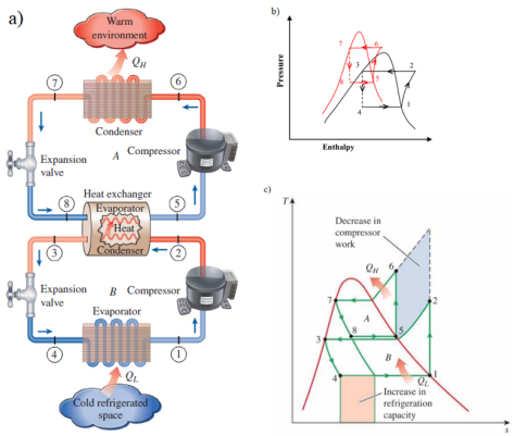
Figure 1 shows the schematic diagram of a typical cascade refrigeration system, with the corresponding p-h plot. The system consists of two coupled vapor compression refrigeration cycles: the LTC and the HTC. These circuits are linked by a cascade condenser, which acts as a condenser for the LTC and an evaporator for the HTC
| [2] | Çengel, Y. A., Boles, M. A. Thermodynamics: An Engineering Approach, 8th ed. McGraw-Hill Education, New York, 2015. |
[2]
.
In LTC, refrigerants such as R-13, R-23, R-170, or R-290 absorb heat from the refrigerated space at an evaporator temperature. The vapor is compressed, with work supplied to the LTC compressor. The compressed refrigerant rejects heat in the cascade condenser at temperature, which is absorbed by the HTC refrigerant (R-134a) at temperature. The HTC refrigerant, after absorbing heat, evaporates and enters the HTC compressor, where work is applied.
The HTC refrigerant condenses by rejecting heat at condenser temperature. The temperature difference between the LTC condenser and the HTC evaporator, denoted by, plays a critical role in determining overall system performance.
Table 1.
Thermo physical properties of R13, R23, R134a, R170, and R290 | [4] | J. M. Calm and G. C. Hourahan, "Physical, Safety, and Environmental Data for Current and Alternative Refrigerants," paper ICR11-915, Proceedings of the 23rd International Congress of Refrigeration, Prague, Czech Republic, Aug. 21–26, 2011, International Institute of Refrigeration (IIR), Paris, France, 2011. |
Refrigerant | Molecular mass (gm/mol) | Critical temperature (°C) | Boiling Point (°C) | ASHRAE safety code | ODP | GWP |
R13 | 104.46 | 28.9 | -81.3 | A1 | 1 | 14000 |
R23 | 70.01 | 25.9 | -82.1 | A1 | 0 | 12000 |
R134a | 102.03 | 101.1 | -26.1 | A1 | 0 | 1300 |
R170 | 30.07 | 32.2 | −88.9 | A3 | 0 | ~20 |
R290 | 44.10 | 96.7 | -42.2 | A3 | 0 | ~20 |
1.2. Refrigerant Selection for Lower Circuit
The selection of refrigerants for the lower-temperature circuit plays a pivotal role in achieving the desired ultra-low temperatures while maintaining energy efficiency and environmental compliance. A comparative analysis of refrigerant properties is presented in
Table 1 to highlight the advantages and limitations of each refrigerant used in the study. For this study, R-13 has been selected for the lower circuit due to its favorable thermodynamic properties, including a low boiling point and high latent heat of vaporization. R-13 exhibits stable performance at temperatures as low as -80°C, making it a suitable candidate for vaccine storage and cryogenic applications.
In addition to R-13, alternative refrigerants such as R-23, R-170, and R-290 will be analyzed. R-23 is commonly used in low-temperature applications but presents higher global warming potential (GWP)
. R-170 (ethane) is a natural refrigerant with low GWP and excellent thermodynamic efficiency, though its flammability requires careful handling. R-290 (propane) is another environmentally friendly option, offering high efficiency at low cost, albeit with limitations related to its flammability and pressure characteristics
| [15] | Blanco Ojeda, F. W. A., et al. Experimental evaluation of low-GWP refrigerants R513A, R1234yf and R436A as alternatives for R134a in a cascade refrigeration cycle with R744. Int. J. Refrig. 2022, 144, 175–187.
https://doi.org/10.1016/j.ijrefrig.2022.08.010ph |
[15]
. A comparative analysis of these refrigerants will be conducted to evaluate their COP, mass flow rates, and environmental impact, ultimately identifying the optimal refrigerant for the lower circuit.
1.3. Assumptions in Thermodynamic Analysis
The following assumptions are made to simplify the thermodynamic analysis:
1) Refrigerant properties of R134a and R13 are ideal within the operating temperature and pressure limits.
2) Heat transfer in the evaporator, condenser, and cascade heat exchanger is steady-state and free from external losses.
3) Compressors operate at a constant isentropic efficiency, accounting for irreversibilities.
4) No pressure drops are considered in pipes and system components.
5) Fixed levels of superheating and subcooling are maintained in both circuits for operational stability.
6) A constant temperature difference is assumed in the cascade heat exchanger for efficient heat transfer.
7) The system operates under standard atmospheric pressure without considering ambient temperature fluctuations.
8) Energy balances strictly follow the conservation of energy principles.
These assumptions ensure the system's simplified yet accurate representation for analysis using EES software. These assumptions form the basis for the parametric study and system optimization carried out using EES software. This to isolate key variables, such as the temperature differences, evaporator conditions, and compressor efficiency, which influence the performance of the cascade refrigeration system.
The following sequence of equations was applied for the analysis
| [3] | R. Roy and B. K. Mandal, “Energetic and exergetic performance comparison of cascade refrigeration system using R170-R161 and R41-R404A as refrigerant pairs,” Heat and Mass Transfer/Waerme- und Stoffuebertragung, vol. 55, no. 3, pp. 723–731, Mar. 2019,
https://doi.org/10.1007/s00231-018-2455-7 |
| [5] | H. M. Getu and P. K. Bansal, “Thermodynamic analysis of an R744-R717 cascade refrigeration system,” International Journal of Refrigeration, vol. 31, no. 1, pp. 45–54, Jan. 2008, https://doi.org/10.1016/j.ijrefrig.2007.06.014 |
[3, 5]
.
The mass flow rate in the LTC can be calculated as:
Heat load in cascade heat exchanger can be calculated as:
The mass flow rate in the LTC can be calculated as:
Compressor power consumption in the HTC is given by:
Compressor power consumption in the HTC is given by:
Heat load in the condenser:
COP of the system:
The overall COP of the system is determined by:
2. Thermodynamic Analysis
The thermodynamic analysis of the cascade refrigeration system focuses on the performance evaluation of the two-stage cycle incorporating R-134a in the high-temperature circuit (HTC) and R13 in the low-temperature circuit (LTC). The analysis aims to determine the COP for each stage and the overall system efficiency.
The system operates under specific conditions:
1) Ambient temperature: 30°C
2) Condensation pressure of R-134a: 10 bar
3) Evaporation temperature in the LTC: -80°C
Table 2. The thermodynamic properties and calculated parameters are summarized below.
Parameter | Value | Unit |
Ambient Temperature (T_amb) | 30 | °C |
Condensation Pressure (p6) | 1000 | kPa |
Evaporation Temperature (T1) | -80 | °C |
Intermediate Temperature (T5) | -20 | °C |
Cascade Heat (Q_intermediate) | 30 | kW |
Upper Circuit Heat (Q_upper) | 30 | kW |
Enthalpy at State 1 (h1) | 110.6 | kJ/kg |
Enthalpy at State 4 (h4) | -0.7459 | kJ/kg |
Enthalpy at State 5 (h5) | 238.4 | kJ/kg |
Enthalpy at State 6 (h6) | 280.5 | kJ/kg |
Enthalpy at State 7 (h7) | 107.3 | kJ/kg |
Mass Flow (LTC Compressor) | 1.082 | kg/s |
Mass Flow (HTC Compressor) | 0.7124 | kg/s |
Table 3. COP for the high and low-temperature circuits, as well as the overall system, are computed as:
COP | Value |
COP_Higher | 3.113 |
COP_Lower | 4.016 |
Overall COP | 1.538 |
The results demonstrate that the lower temperature circuit achieves a higher COP compared to the higher temperature circuit, owing to the efficient heat absorption at low temperatures. However, the overall COP reflects the combined influence of both circuits, highlighting the interdependence of the LTC and HTC for effective cascade system performance.
These calculations and the parametric study conducted in EES provide a comprehensive understanding of the thermodynamic behavior of the cascade refrigeration system, enabling design optimization for enhanced efficiency.
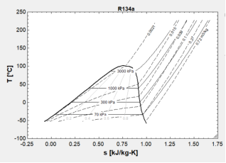
Figure 2. T-s diagram of R-134a used in upper circuit.
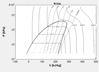
Figure 3. P-h diagram of R-134a used in upper circuit.
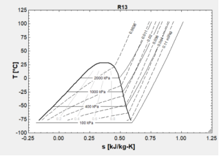
Figure 4. T-s diagram of R-13 used in lower circuit.
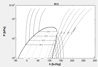
Figure 5. P-h diagram of R-13 used in lower circuit.
The EES-generated thermodynamic diagrams for R-13 (
Figures 4 and 5) and R-134a (
Figures 2 and 3) provide critical insights into the performance and efficiency of the cascade refrigeration system. The pressure-enthalpy (P-h) and temperature-entropy (T-s) diagrams for R-13 clearly illustrate the operational thermodynamic cycle in the lower circuit, covering evaporation, compression, condensation, and expansion phases. These diagrams highlight the refrigerant's behavior under the specified operating conditions, especially at ultra-low temperatures necessary for achieving a target evaporator temperature of -80°C. Similarly, the P-h and T-s diagrams for R-134a demonstrate its thermodynamic performance in the upper circuit, revealing its ability to handle higher condensation pressures while maintaining thermal stability and efficiency. The steep enthalpy gradient in the compression phase of R-134a indicates its suitability for managing heat loads rejected from the lower circuit. These graphical representations not only validate the refrigerants' compatibility with the cascade setup but also aid in visualizing energy transfers, entropy generation, and system efficiency.
3. Parametric Study
The parametric study aims to evaluate the influence of key operating parameters on the performance of the cascade refrigeration system. By varying critical factors such as the evaporator temperature in the LTC, the condensation temperature in the HTC, and ∆T across the cascade heat exchanger, a comprehensive analysis of system performance is conducted. This approach ensures the identification of optimal operating conditions for enhanced COP and energy efficiency.
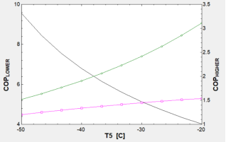
Figure 6. Graphical Representation between varying temperature and COP of lower circuit, upper circuit & overall COP.
Figure 6 represents a comprehensive analysis of the relationship between the lower-circuit evaporator temperature (T5) and the COP for the lower circuit, upper circuit, and the overall cascade refrigeration system. The graphical representation reveals that as the evaporator temperature (T5) decreases from -20°C to -50°C, there is a noticeable decline in both COP
Higher and Overall COP, while COP
Lower exhibits a steady increase. Specifically, COP
Higher reduces from 3.113 at -20°C to 1.519 at -50°C, indicating the increased work required by the higher circuit compressor at lower evaporator temperatures. Similarly, the Overall COP drops from 1.538 at -20°C to 1.202 at -50°C, showcasing the compounded effect of declining efficiency in the upper circuit and increased system load. In contrast, COP
Lower rises significantly from 4.016 to 9.544 within the same temperature range, reflecting the improved performance of the lower circuit in achieving lower temperatures with higher efficiency. These trends emphasize the delicate balance required between the upper and lower circuits for optimizing system performance and the critical role of intermediate operating conditions in achieving an optimal Overall COP.
Analyzing the relationship between the evaporator and compressor mass flow rates as a function of the evaporator temperature (T5), using data and graphical outputs derived from EES.
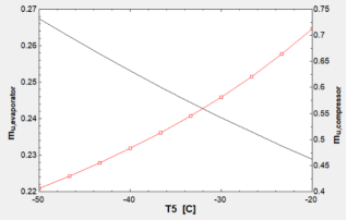
Figure 7. Graphical Representation between varying temperature and mass flow rate of evaporator and compressor.
Graphical results (
Figure 7) indicate that as the evaporator temperature (T5) decreases from -20°C to -50°C, there is a distinct trend observed in the refrigerant mass flow rates. The mass flow rate of the ṁ
u,evp steadily increases with decreasing evaporator temperature, rising from 0.2289 kg/s at -20°C to 0.2674 kg/s at -50°C. This trend can be attributed to the increased refrigeration load in the lower-temperature circuit at lower evaporation temperatures, which requires higher refrigerant flow to sustain the desired cooling effect. Conversely, the compressor mass flow rate ṁ
u,comp demonstrates a gradual decline, decreasing from 0.7124 kg/s at -20°C to 0.4063 kg/s at -50°C. This inverse relationship suggests that the required work input to the compressor is reduced as the temperature approaches ultra-low conditions, indicating improved thermodynamic efficiency under these specific operational conditions. The graphical representation reinforces these findings, with the red curve indicating the upward trend of ṁ
u,evp and the black curve highlighting the downward trend of ṁ
u,comp. These contrasting trends reflect the interplay between system demand and refrigerant dynamics within the cascade refrigeration system.
Varying ambient temperatures
The parametric study also examines the influence of varying ambient temperatures (25°C, 30°C, and 35°C) on the performance of the cascade refrigeration system, specifically focusing on the system's COP and the intermediate heat exchanger's behavior. The system utilizes R-134a as the refrigerant in the upper-temperature circuit and R13 in the lower-temperature circuit. EES was employed to calculate key parameters for each ambient temperature, with the results highlighting distinct trends in system performance metrics.
Table 4. Impact of ambient temperature on the system's COP and intermediate heat exchanger performance.
Parameter | Ambient Temperature: 25°C | Ambient Temperature: 30°C | Ambient Temperature: 35°C |
COPHigher | 3.113 | 3.113 | 3.113 |
COPLower | 4.016 | 4.016 | 4.016 |
COPoverall | 1.538 | 1.538 | 1.538 |
ṁl,evp | 0.2426 | 0.2695 | 0.2965 |
ṁu,comp | 0.6412 | 0.7124 | 0.7837 |
Qintermediate | 30 | 30 | 33 |
From
Table 4, it is observed that the overall COP decreases as the ambient temperature increases. At an ambient temperature of 25°C, the overall COP is 1.538, and it remains consistent at 1.538 for 30°C and 35°C due to constant values for the higher and lower circuit COPs (COP
Higher= 3.113 and COP
Lower= 4.016). However, ṁ
u,comp rises significantly with an increase in ambient temperature, from 0.6412 kg/s at 25°C to 0.7837 kg/s at 35°C. Similarly, ṁ
l,evp increases from 0.2426 kg/s at 25°C to 0.2965 kg/s at 35°C, indicating a higher cooling demand under elevated ambient temperatures. These trends suggest that while the system maintains efficiency at varying ambient conditions, the refrigeration load and corresponding refrigerant flow rates in both circuits are strongly dependent on ambient temperature.
The intermediate heat exchanger's performance, represented by the heat transferred Qintermediate also exhibits a slight variation with temperature. At 25°C and 30°C, the intermediate heat transfer rate is approximately 30 kW, while at 35°C, it rises to 33 kW, reflecting the increased thermal load at higher ambient temperatures.
These findings underscore the critical role of ambient temperature in determining the operational parameters of the cascade refrigeration system. The observed variations in refrigerant mass flow rates and heat exchanger performance highlight the need for precise system design and optimization under specific environmental conditions to achieve desired operational efficiency
| [7] | Ji, S., Liu, Z., Pan, H., Li, X. Energy, exergy, environmental and exergoeconomic (4E) analysis of an ultra-low temperature cascade refrigeration system with environmental-friendly refrigerants. Appl. Therm. Eng. 2024, 248, 123210.
https://doi.org/10.1016/j.applthermaleng.2024.123210 |
[7]
.
4. Performance Comparison
In this study, the performance of the cascade refrigeration system is evaluated by investigating four different refrigerants (R13, R23, R170, and R290) in the lower-temperature circuit while maintaining R-134a in the upper-temperature circuit. The results obtained from the EES analysis reveal substantial differences in the system’s COP and refrigerant mass flow rates, depending on the refrigerant type. These variations stem from the thermophysical properties of each refrigerant, which significantly impact the system’s performance under identical operating conditions
.
Table 5. System performance Comparison for three different refrigerants.
Parameter | R13 | R23 | R170 | R290 |
COPHIGHER | 3.113 | 3.113 | 3.113 | 3.113 |
COPLOWER | 4.016 | 5.758 | 4.974 | 4.914 |
Overall COP | 1.538 | 1.816 | 1.704 | 1.695 |
ṁl,evp | 0.2695 | 0.2289 | 0.07656 | 0.0774 |
ṁl,comp | 0.7124 | 0.7124 | 0.3080 | 0.3804 |
Qintermediate (kW) | 30 | 30 | 30 | 30 |
The results extracted from the EES solution (refer to
Table 5) reveal significant variations in COP when different refrigerants are used in the lower-temperature circuit. When R13 is used in the lower circuit, the overall COP is recorded as 1.538, with a lower circuit COP of 4.016. The mass flow rates of the evaporator (ṁ
l,evp) and the compressor (ṁ
l,comp) are 0.2695 kg/s and 0.7124 kg/s, respectively. In contrast, using R23 improves the overall COP to 1.816 due to a higher lower-circuit COP of 5.758. The mass flow rates remain consistent for the compressor but slightly increase for the evaporator, indicating better performance characteristics of R23. On the other hand, refrigerants R170 and R290 result in lower overall COPs of 1.704 and 1.695, respectively, with lower-circuit COP values of 4.974 and 4.914. This reduction is primarily due to their lower efficiency in transferring heat compared to R23. Additionally, the mass flow rates of the evaporator and compressor are reduced with R170 and R290, which suggests lower cooling capacities relative to R13 and R23.
Optimal Refrigerant Selection
The results demonstrate that R23 offers the highest overall COP, making it the most efficient refrigerant for the lower circuit among the four tested. However, R170 and R290 still present viable alternatives due to their environmental benefits and lower global warming potential (GWP). The heat transfer in the intermediate heat exchanger remains consistent across all cases at 30 kW, indicating that the upper circuit performance is unaffected by the choice of refrigerant in the lower circuit. These findings emphasize the critical need for selecting appropriate refrigerants in the design of cascade refrigeration systems to balance efficiency, environmental impact, and operational requirements
| [11] | Kumar, S., Gahlot, P., Kumar, S. Exergetic sustainability and environmental impact index analysis to reduce carbon footprints of ultra-low temperature cascade refrigeration. J. Therm. Anal. Calorim. 2025, 150(6), 4535–4548.
https://doi.org/10.1007/s10973-025-14021-1 |
[11]
.
5. Cooling Load and Heat Transfer Calculation
The cooling load for the cascade refrigerator is determined based on heat transfer through the insulated walls from the ambient temperature (Tambient= 40°C) to the internal temperature (Tinternal= - 80°C). The insulation is assumed to be uniform across all six walls with a thermal conductivity (k = 0.025 kW/mK), thickness (d = 0.25 m), and a total surface area (A = 6 m2). The heat transfer rate (Qtotal) is calculated using Fourier’s law for steady-state heat conduction:
Substituting the values:
Thus, the cooling load for the refrigerator is 72 kW. This load must be managed by the cascade refrigeration system, which uses R-134a in the upper-temperature circuit and R13 in the lower-temperature circuit. Proper selection of components ensures the system's ability to handle this load efficiently.
Insulation Material
The insulation material plays a critical role in reducing heat transfer and minimizing cooling load. Polyurethane foam (PUF) is widely used due to its low thermal conductivity (k = 0.025 W/mK), lightweight, and durability. It is suitable for temperatures as low as −100°C.
6. Conclusion
The performance analysis of the cascade refrigeration system using R-134a in the upper-temperature circuit and four different refrigerants (R-13, R-23, R-170, R-290) in the lower-temperature circuit reveals key insights into system efficiency and thermodynamic behavior. The results demonstrate that R-23 exhibits the highest overall COP of 1.816, making it the most efficient refrigerant for the lower circuit, while R-13 shows a moderate COP of 1.538. Conversely, R-170 and R-290 yield lower efficiencies, with overall COPs of 1.704 and 1.695, respectively. The heat transfer analysis highlights the impact of ambient temperature and insulation properties on system performance, indicating that lower thermal conductivity and greater insulation thickness significantly reduce heat load. This study underscores the critical role of refrigerant selection in optimizing cascade refrigeration systems, providing a pathway to improve energy efficiency and adapt to varying operational conditions
| [12] | Hamzaoui, M., Tiachacht, S., Hadiouche, A. Optimization of a three-stage cascade refrigeration system operating with natural refrigerants to produce low temperatures by applying a bio-inspired method. Therm. Sci. Eng. Progress 2024, 50, 102519. https://doi.org/10.1016/j.tsep.2024.102519 |
| [14] | Kumar, S., Kumar, A., Gahlot, P. Thermodynamic performance analysis of cascade refrigeration cycle operating with different refrigerant blends of CO2. Natl. Acad. Sci. Lett. 2025. https://doi.org/10.1007/s40009-025-01736-w |
[12, 14]
.
Abbreviations
COP | Co-efficient of Performance |
CRS | Cascade Refrigeration System |
GWP | Global Warming Potential |
ODP | Ozone Depletion Potential |
LTC | Low Temperature Cycle |
HTC | High Temperature Cycle |
EES | Engineering Equation Solver |
Qeva | Evaporator Heat Load in kW |
Qcas | Cascade Condenser Heat Load in kW |
Qcond | Condenser Heat Load in kW |
WH | Compressor Work in Htc in kw |
WL | Compressor Work in Ltc in Kw |
ṁu,evp | Mass Flowrate of Upper Evaporator (kgs-1) |
ṁu,comp | Mass Flowrate of Upper Compressor (kgs-1) |
ṁl,evp | Mass Flowrate of Lower Evaporator (kgs-1) |
ṁl,comp | Mass Flowrate of Lower Compressor (kgs-1) |
ΔT | Temperature Difference |
h | Specific Enthalpy in kJ/ kg |
hs | specific Enthalpy Calculated at Suction Entropy (kJ kg 1) |
s | Specific Entropy in kJ/ kg – K |
ṁ | Mass Flowrate (kgs-1) |
P | Pressure (kPa) |
Q | Rate of Heat Transfer (kW) |
Author Contributions
Ronit Singh BK: Conceptualization, Resources, Methodology, Software, Formal analysis, Investigation, Data curation
Conflicts of Interest
The authors declare no conflicts of interest.
Appendix
EES CODE:
"Design of cascade Refrigeration system"
"For higher circuit"
"For stage 5"
T5 = -20 [c]{since R134a is used assume the temperature of the upper circuit evaporator be - 20 }
x5 = 1
h5 =enthalpy(R134a,T=T5,x=x5)
s5 = entropy(R134a,T=T5,x=x5)
"For stage 6"
p6 = 1000 [kpa]
s6 = s5
t6 = temperature(R134a,P=P6,s=s6)
h6 =enthalpy(R134a,P=P6,s=s6)
"For stage 7"
x7 = 0
p7 = p6
h7 = enthalpy(R134a,P=P7,x=x7)
h8 = h7
COP_HIGHER = (h5-h8)/(h6-h5)
"For lower circuit"
"For stage 1"
x1 = 1
t1 = -80 [c] {using R-23 as refrigerant whose mini boiling temp is -80 c so since we need -80 assuming -80 c}
h1 = enthalpy(R13,T=T1,x=x1)
s1 = entropy(R13,T=T1,x=x1)
"For stage 2"
s2 = s1
t2 = t5
h2 = enthalpy(R13,T=T2,s=s2)
p2 = pressure(R13,T=T2,s=s2)
"For stage 3"
p3 = p2
x3 = 0
h3 =enthalpy(R13,P=P3,x=x3)
h4 = h3
COP_LOWER = (h1 - h4)/(h2-h1)
OVERALL_COP = (COP_LOWER*COP_HIGHER)/(1+COP_LOWER+COP_HIGHER)
"According to the question ambient temp is 30 so "
t_delta = 30+20
d = 0.25 [m^2] {insulation thckness}
l = 1 [m]
A = 6*L^2 {Surface area of cubiod room}
k = 0.025 {insluation thermal conductivity}
Q_U = (K*A*t_delta)/d
"Calculating mass flow rate in upper circuit"
m_u_evaporator = (Q_U)/(h5-h8)
m_u_compressor = (Q_U)/(h6-h5)
m_l_evaporator = (Q_U)/(h1-h4)
m_l_compressor = (Q_U)/(h2-h1)
"since the heat rejected by lower cirucit is equals to heat absorbed by upper circuit"
Q_Upper = m_u_evaporator *(h5-h8)
Q_Lower = Q_Upper
Q_intermediate = Q_Upper
References
| [1] |
A. Da Silva, E. P. Bandarra Filho, and A. H. P. Antunes, “Comparison of a R744 cascade refrigeration system with R404A and R22 conventional systems for supermarkets,” in Applied Thermal Engineering, Aug. 2012, pp. 30–35.
https://doi.org/10.1016/j.applthermaleng.2011.12.019
|
| [2] |
Çengel, Y. A., Boles, M. A. Thermodynamics: An Engineering Approach, 8th ed. McGraw-Hill Education, New York, 2015.
|
| [3] |
R. Roy and B. K. Mandal, “Energetic and exergetic performance comparison of cascade refrigeration system using R170-R161 and R41-R404A as refrigerant pairs,” Heat and Mass Transfer/Waerme- und Stoffuebertragung, vol. 55, no. 3, pp. 723–731, Mar. 2019,
https://doi.org/10.1007/s00231-018-2455-7
|
| [4] |
J. M. Calm and G. C. Hourahan, "Physical, Safety, and Environmental Data for Current and Alternative Refrigerants," paper ICR11-915, Proceedings of the 23rd International Congress of Refrigeration, Prague, Czech Republic, Aug. 21–26, 2011, International Institute of Refrigeration (IIR), Paris, France, 2011.
|
| [5] |
H. M. Getu and P. K. Bansal, “Thermodynamic analysis of an R744-R717 cascade refrigeration system,” International Journal of Refrigeration, vol. 31, no. 1, pp. 45–54, Jan. 2008,
https://doi.org/10.1016/j.ijrefrig.2007.06.014
|
| [6] |
Tan, H., Bai, M., Xu, L., Li, X., Liu, Z. Experimental study on the pull-down performance of a −80°C cascade refrigeration freezer. Asia-Pac. J. Chem. Eng. 2023, 18(3), e2888.
https://doi.org/10.1002/apj.2888
|
| [7] |
Ji, S., Liu, Z., Pan, H., Li, X. Energy, exergy, environmental and exergoeconomic (4E) analysis of an ultra-low temperature cascade refrigeration system with environmental-friendly refrigerants. Appl. Therm. Eng. 2024, 248, 123210.
https://doi.org/10.1016/j.applthermaleng.2024.123210
|
| [8] |
Lee, S.-B., Shin, C.-H., Lee, J.-H. A Novel Approach of −80°C Cascade Refrigeration System Using Non-Flammable Quaternary Refrigerants for Semiconductor Process Applications. Energies 2024, 17(23), 6178.
https://doi.org/10.3390/en17236178
|
| [9] |
Kumar, S., Gahlot, P., Kumar, S. A novel ultra-low temperature cascade refrigeration with dual auxiliary loop to enhance thermal performance. Sci. Rep. 2025, 15, 23214.
https://doi.org/10.1038/s41598-025-08462-9
|
| [10] |
Udroiu, C.-M., Mota-Babiloni, A., Navarro-Esbrí, J. Advanced two-stage cascade configurations for energy-efficient −80°C refrigeration. Energy Convers. Manage. 2022, 267, 115907.
https://doi.org/10.1016/j.enconman.2022.115907
|
| [11] |
Kumar, S., Gahlot, P., Kumar, S. Exergetic sustainability and environmental impact index analysis to reduce carbon footprints of ultra-low temperature cascade refrigeration. J. Therm. Anal. Calorim. 2025, 150(6), 4535–4548.
https://doi.org/10.1007/s10973-025-14021-1
|
| [12] |
Hamzaoui, M., Tiachacht, S., Hadiouche, A. Optimization of a three-stage cascade refrigeration system operating with natural refrigerants to produce low temperatures by applying a bio-inspired method. Therm. Sci. Eng. Progress 2024, 50, 102519.
https://doi.org/10.1016/j.tsep.2024.102519
|
| [13] |
Lin, X., Yu, F., Yu, J. Thermodynamic analysis of a modified auto-cascade refrigeration cycle using mixture R290/R170. Appl. Therm. Eng. 2025, 280, 128558.
https://doi.org/10.1016/j.applthermaleng.2025.128558
|
| [14] |
Kumar, S., Kumar, A., Gahlot, P. Thermodynamic performance analysis of cascade refrigeration cycle operating with different refrigerant blends of CO2. Natl. Acad. Sci. Lett. 2025.
https://doi.org/10.1007/s40009-025-01736-w
|
| [15] |
Blanco Ojeda, F. W. A., et al. Experimental evaluation of low-GWP refrigerants R513A, R1234yf and R436A as alternatives for R134a in a cascade refrigeration cycle with R744. Int. J. Refrig. 2022, 144, 175–187.
https://doi.org/10.1016/j.ijrefrig.2022.08.010ph
|
Cite This Article
-
APA Style
Bk, R. S. (2026). Design Optimization and Performance Evaluation of a Cascade Refrigeration System for Ultra-Low Temperature Applications. International Journal of Fluid Mechanics & Thermal Sciences, 12(3), 76-85. https://doi.org/10.11648/j.ijfmts.20261203.13
 Copy
|
Copy
|
 Download
ACS Style
Bk, R. S. Design Optimization and Performance Evaluation of a Cascade Refrigeration System for Ultra-Low Temperature Applications. Int. J. Fluid Mech. Therm. Sci. 2026, 12(3), 76-85. doi: 10.11648/j.ijfmts.20261203.13
Copy
|
Download
AMA Style
Bk RS. Design Optimization and Performance Evaluation of a Cascade Refrigeration System for Ultra-Low Temperature Applications. Int J Fluid Mech Therm Sci. 2026;12(3):76-85. doi: 10.11648/j.ijfmts.20261203.13
Copy
|
Download
-
@article{10.11648/j.ijfmts.20261203.13,
  author = {Ronit Singh Bk},
  title = {Design Optimization and Performance Evaluation of a Cascade Refrigeration System for Ultra-Low Temperature Applications},
  journal = {International Journal of Fluid Mechanics & Thermal Sciences},
  volume = {12},
  number = {3},
  pages = {76-85},
  doi = {10.11648/j.ijfmts.20261203.13},
  url = {https://doi.org/10.11648/j.ijfmts.20261203.13},
  eprint = {https://article.sciencepublishinggroup.com/pdf/10.11648.j.ijfmts.20261203.13},
  abstract = {This study presents the design and performance analysis of a cascade refrigeration system aimed at achieving ultra-low temperatures of -80°C, essential for vaccine storage and cryogenic applications. Cascade refrigeration systems are widely used for such applications because they reduce compressor work and improve overall efficiency compared to single-stage systems, particularly when a large temperature lift is required. The system analyzed in this study utilizes R-134a in the upper-temperature circuit and investigates the performance of four candidate refrigerants — R-13, R-23, R-170, and R-290 — in the lower-temperature circuit. Thermodynamic simulations were conducted using Engineering Equation Solver (EES) to determine the coefficient of performance (COP) of each circuit and the overall system, along with the corresponding refrigerant mass flow rates, under a fixed set of operating conditions. The results show that R-23 yields the highest overall COP of 1.816, outperforming R-13 (1.538), R-170 (1.704), and R-290 (1.695), owing to its superior lower-circuit COP of 5.758. A parametric study further examined the effect of evaporator temperature and ambient temperature on system performance, showing that overall COP declines as the evaporator temperature is lowered from -20°C to -50°C, while the lower-circuit COP improves over the same range. Heat transfer analysis highlights the significance of insulation properties, with an estimated cooling load of 72 kW for a 1 m³ chamber at an ambient temperature of 40°C, based on a polyurethane foam insulation layer of 0.25 m thickness. The findings emphasize the critical role of refrigerant selection in enhancing efficiency and operational stability, contributing to sustainable and energy-efficient refrigeration solutions for ultra-low-temperature storage applications such as vaccine preservation.},
 year = {2026}
}
Copy
|
Download
-
TY  - JOUR
T1  - Design Optimization and Performance Evaluation of a Cascade Refrigeration System for Ultra-Low Temperature Applications
AU  - Ronit Singh Bk
Y1  - 2026/09/30
PY  - 2026
N1  - https://doi.org/10.11648/j.ijfmts.20261203.13
DO  - 10.11648/j.ijfmts.20261203.13
T2  - International Journal of Fluid Mechanics & Thermal Sciences
JF  - International Journal of Fluid Mechanics & Thermal Sciences
JO  - International Journal of Fluid Mechanics & Thermal Sciences
SP  - 76
EP  - 85
PB  - Science Publishing Group
SN  - 2469-8113
UR  - https://doi.org/10.11648/j.ijfmts.20261203.13
AB  - This study presents the design and performance analysis of a cascade refrigeration system aimed at achieving ultra-low temperatures of -80°C, essential for vaccine storage and cryogenic applications. Cascade refrigeration systems are widely used for such applications because they reduce compressor work and improve overall efficiency compared to single-stage systems, particularly when a large temperature lift is required. The system analyzed in this study utilizes R-134a in the upper-temperature circuit and investigates the performance of four candidate refrigerants — R-13, R-23, R-170, and R-290 — in the lower-temperature circuit. Thermodynamic simulations were conducted using Engineering Equation Solver (EES) to determine the coefficient of performance (COP) of each circuit and the overall system, along with the corresponding refrigerant mass flow rates, under a fixed set of operating conditions. The results show that R-23 yields the highest overall COP of 1.816, outperforming R-13 (1.538), R-170 (1.704), and R-290 (1.695), owing to its superior lower-circuit COP of 5.758. A parametric study further examined the effect of evaporator temperature and ambient temperature on system performance, showing that overall COP declines as the evaporator temperature is lowered from -20°C to -50°C, while the lower-circuit COP improves over the same range. Heat transfer analysis highlights the significance of insulation properties, with an estimated cooling load of 72 kW for a 1 m³ chamber at an ambient temperature of 40°C, based on a polyurethane foam insulation layer of 0.25 m thickness. The findings emphasize the critical role of refrigerant selection in enhancing efficiency and operational stability, contributing to sustainable and energy-efficient refrigeration solutions for ultra-low-temperature storage applications such as vaccine preservation.
VL  - 12
IS  - 3
ER  -
Copy
|
Download





 Share This Article
 Twitter
 Linked In
 Facebook