
Grid-tied inverters serve as key equipment to guarantee the reliable operation of modern power systems dominated by renewable energy sources. Under asymmetric grid conditions, injecting negative-sequence current is a widely adopted control strategy for three-level grid-connected inverters to suppress grid voltage unbalance. However, this paper discovers an unreported phenomenon that obvious 50 Hz fluctuations arise in the half DC-bus voltage of three-level inverters during negative-sequence current injection. To clarify the generation mechanism of this voltage fluctuation, Fourier series decomposition is employed to analyze the coupling relationship between sequence components of voltage and current. The theoretical analysis demonstrates that the interaction between negative-sequence voltage and negative-sequence current constitutes the primary cause of the 50 Hz oscillation on the half DC-link voltage. Based on the revealed mechanism, the allowable safe operating range of the half DC-bus voltage is deduced quantitatively. Finally, simulation tests are carried out in the MATLAB/Simulink environment. The obtained results verify the correctness of the theoretical derivation and the proposed operating range constraint. This work provides a theoretical reference for parameter design and stable operation of three-level grid-tied inverters under unbalanced grid faults.
| Published in | American Journal of Energy Engineering (Volume 14, Issue 4) |
| DOI | 10.11648/j.ajee.20261404.11 |
| Page(s) | 172-178 |
| Creative Commons |
This is an Open Access article, distributed under the terms of the Creative Commons Attribution 4.0 International License (http://creativecommons.org/licenses/by/4.0/), which permits unrestricted use, distribution and reproduction in any medium or format, provided the original work is properly cited. |
| Copyright |
Copyright © The Author(s), 2026. Published by Science Publishing Group |
Three-level Inverters, Dc-link Voltage, Negative-sequence Current, 50Hz Fluctuations
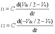 (1)
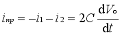 (2)
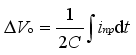 (3)
 (4)
 (5)
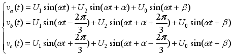 (6)
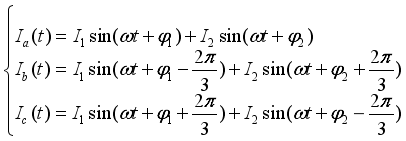 (7)
 ,
 and
 . Taking
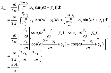
 as an example, the derivation is as shown in Equation(A-1) of the Appendix. Where the expression of phase γb is
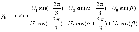 (8)
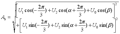 (9)
 (10)
 can be expressed as:
 (11)
 (12)
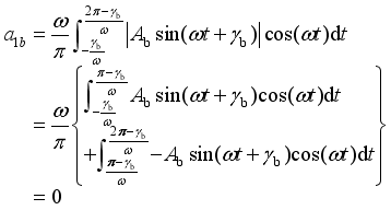 (13)
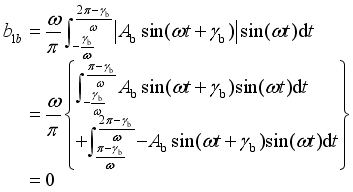 (14)
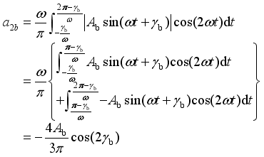 (15).
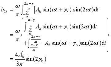 (16)
 (17)
 (18)
 (19)
 (20)
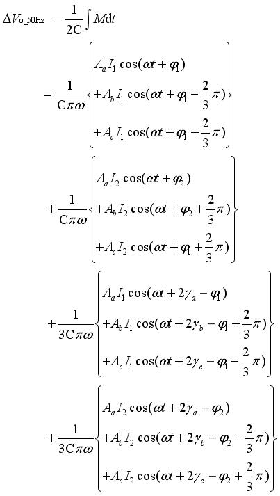 (21)
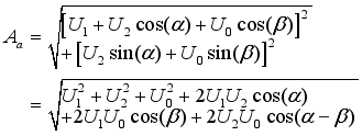 (22)
 (23)
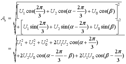 (24)
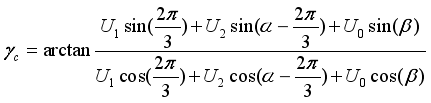 (25)
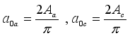 (26)
 (27)
 (28)
 (29)
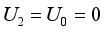 , can be simplified as:
 (30)
PCC | Point of Common Coupling |
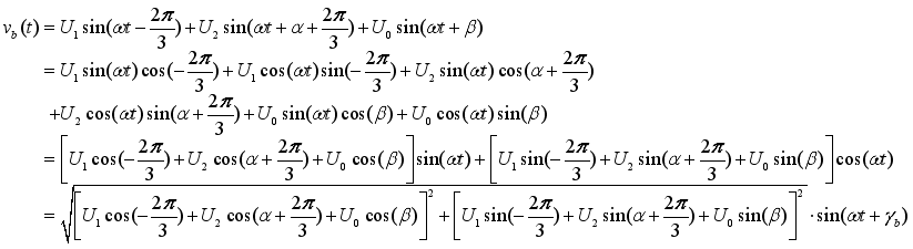 (A-1)
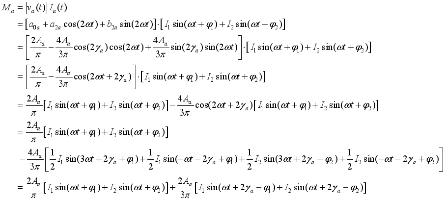 (A-2)
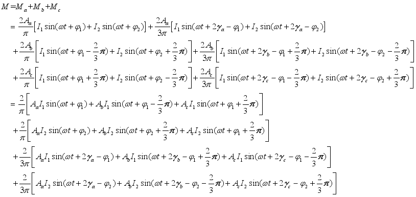 (A-3)
| [1] | J. Zhou, J. O. Ojo, F. Tang, J. Haruna and P. C. Loh, "A Carrier-Based Discontinuous PWM for Single and Parallel Three-Level T-Type Converters With Neutral-Point Potential Balancing," IEEE Trans. on Ind. Appl., vol. 57, no. 5, pp. 5117-5127, Sept.-Oct. 2021. |
| [2] | G. Zhang, Y. Liu, X. Gu, W. Huang and W. Chen, "Carrier-Based PWM Strategy of Three-Level Neutral-Point-Clamped Inverter With Optimal Extension Mode," IEEE Trans. on Power Electron., vol. 40, no. 5, pp. 5821-5832, May 2025. |
| [3] | L. Ha, H. Wang, M. Su, Y. Liu and Z. Zeng, "An Adaptive Power Decoupling Control for Three-Level NPC Converter Under Unbalanced Grid," IEEE J. Emerg. Sel. Topics Power Electron., vol. 13, no. 2, pp. 1945-1956, Apr. 2025. |
| [4] | W. Yan, R. Dian, Y. Li, Z. Liu and M. F. Elmorshedy, "DC-Link Balancing Control Based on ADRC for Three-Level NPC Inverter," IEEE Trans. on Power Electron., vol. 41, no. 3, pp. 3208-3219, Mar. 2026. |
| [5] | J. Wang, Y. Gao and W. Jiang, "A Carrier-Based Implementation of Virtual Space Vector Modulation for Neutral-Point-Clamped Three-Level Inverter," IEEE Trans. Ind. Electron, vol. 64, no. 12, pp. 9580-9586, Dec. 2017. |
| [6] | I. M. Alsofyani and K. -B. Lee, "Simple Capacitor Voltage Balancing for Three-Level NPC Inverter Using Discontinuous PWM Method With Hysteresis Neutral-Point Error Band," IEEE Trans. on Power Electron., vol. 36, no. 11, pp. 12490-12503, Nov. 2021, |
| [7] | W. Jiang, Q. Zhang, M. Mingna and X. Huang, "Low Frequency Harmonics Reduction Discontinuous PWM Strategy With Active Neutral Point Voltage Control for Neutral Point Clamped Three-Level Inverter," in IEEE Access, vol. 8, pp. 179128-179140, 2020. |
| [8] | J. Pou, R. Pindado, D. Boroyevich and P. Rodriguez, “Evaluation of the low-frequency neutral-point voltage oscillations in the three-level inverter,” IEEE Trans. Ind. Electron., vol. 52, no. 6, pp. 1582-1588, Dec. 2005. |
| [9] | J. S. Lee and K. B. Lee, “New modulation techniques for a leakage current reduction and a neutral-point voltage balance in transformerless photovoltaic systems using a three-level inverter,”IEEE Trans. Power Electron., vol. 29, no. 4, pp. 1720–1732, Apr. 2014. |
| [10] | P. Alemi, Y.-C. Jeung, and D.-C. Lee, “DC-link capacitance minimization in T-type three-level AC/DC/AC PWM converters,”IEEE Trans. Power Electron., vol. 62, no. 3, pp. 1382–1391, Mar. 2015. |
| [11] | X. Wu, G. Tan, Z. Ye, G. Yao, Z. Liu, and G. Liu, “A virtual-spacevector PWM for three-level neutral-point-clamped inverter with unbalanced DC-links,” IEEE Trans. Power Electron., vol. 33, no. 3, pp. 2630–2642, Mar. 2018. |
| [12] | T. Ghennam, E. M. Berkouk, and B. Francois, “A novel space-vector current control based on circular hysteresis areas of a three-phase neutral point-clamped inverter,” IEEE Trans. Ind. Electron., vol. 57, no. 8, pp. 2669–2678, Aug. 2010. |
| [13] | S. K. Giri, S. Chakrabarti, S. Banerjee, and C. Chakraborty, “A carrier-based PWM scheme for neutral point voltage balancing in three-level inverter extending to full power factor range,” IEEE Trans. Ind. Electron., vol. 64, no. 3, pp. 1873–1883, Mar. 2017. |
| [14] | R. A. Ghaderloo, Y. Shen, H. Wang and A. Khaligh, "Carrier-Based Continuous PWM for Compensating the Effect of Unbalanced and Oscillating Neutral-Point Voltage in T-Type Inverter," IEEE Trans. Transp. Electrific., vol. 11, no. 4, pp. 2312-2323, Aug. 2025. |
| [15] | G. Zhang, Y. Liu, X. Gu, W. Huang and W. Chen, "Carrier-Based PWM Strategy of Three-Level Neutral-Point-Clamped Inverter With Optimal Extension Mode," IEEE Open J. Power Electron., vol.7, pp.1738-1752, May 2026. |
APA Style
Luo, C., Cao, J., Qi, M., Lu, D., Zhou, H. (2026). Analysis of 50 Hz Neutral-Point Voltage Fluctuation of DC-Link Capacitors for Three-level Inverters. American Journal of Energy Engineering, 14(4), 172-178. https://doi.org/10.11648/j.ajee.20261404.11
ACS Style
Luo, C.; Cao, J.; Qi, M.; Lu, D.; Zhou, H. Analysis of 50 Hz Neutral-Point Voltage Fluctuation of DC-Link Capacitors for Three-level Inverters. Am. J. Energy Eng. 2026, 14(4), 172-178. doi: 10.11648/j.ajee.20261404.11
@article{10.11648/j.ajee.20261404.11,
  author = {Cheng Luo and Jianbo Cao and Mi Qi and Dapeng Lu and Hongwei Zhou},
  title = {Analysis of 50 Hz Neutral-Point Voltage Fluctuation of
DC-Link Capacitors for Three-level Inverters},
  journal = {American Journal of Energy Engineering},
  volume = {14},
  number = {4},
  pages = {172-178},
  doi = {10.11648/j.ajee.20261404.11},
  url = {https://doi.org/10.11648/j.ajee.20261404.11},
  eprint = {https://article.sciencepublishinggroup.com/pdf/10.11648.j.ajee.20261404.11},
  abstract = {Grid-tied inverters serve as key equipment to guarantee the reliable operation of modern power systems dominated by renewable energy sources. Under asymmetric grid conditions, injecting negative-sequence current is a widely adopted control strategy for three-level grid-connected inverters to suppress grid voltage unbalance. However, this paper discovers an unreported phenomenon that obvious 50 Hz fluctuations arise in the half DC-bus voltage of three-level inverters during negative-sequence current injection. To clarify the generation mechanism of this voltage fluctuation, Fourier series decomposition is employed to analyze the coupling relationship between sequence components of voltage and current. The theoretical analysis demonstrates that the interaction between negative-sequence voltage and negative-sequence current constitutes the primary cause of the 50 Hz oscillation on the half DC-link voltage. Based on the revealed mechanism, the allowable safe operating range of the half DC-bus voltage is deduced quantitatively. Finally, simulation tests are carried out in the MATLAB/Simulink environment. The obtained results verify the correctness of the theoretical derivation and the proposed operating range constraint. This work provides a theoretical reference for parameter design and stable operation of three-level grid-tied inverters under unbalanced grid faults.},
 year = {2026}
}
TY  - JOUR
T1  - Analysis of 50 Hz Neutral-Point Voltage Fluctuation of
DC-Link Capacitors for Three-level Inverters
AU  - Cheng Luo
AU  - Jianbo Cao
AU  - Mi Qi
AU  - Dapeng Lu
AU  - Hongwei Zhou
Y1  - 2026/11/10
PY  - 2026
N1  - https://doi.org/10.11648/j.ajee.20261404.11
DO  - 10.11648/j.ajee.20261404.11
T2  - American Journal of Energy Engineering
JF  - American Journal of Energy Engineering
JO  - American Journal of Energy Engineering
SP  - 172
EP  - 178
PB  - Science Publishing Group
SN  - 2329-163X
UR  - https://doi.org/10.11648/j.ajee.20261404.11
AB  - Grid-tied inverters serve as key equipment to guarantee the reliable operation of modern power systems dominated by renewable energy sources. Under asymmetric grid conditions, injecting negative-sequence current is a widely adopted control strategy for three-level grid-connected inverters to suppress grid voltage unbalance. However, this paper discovers an unreported phenomenon that obvious 50 Hz fluctuations arise in the half DC-bus voltage of three-level inverters during negative-sequence current injection. To clarify the generation mechanism of this voltage fluctuation, Fourier series decomposition is employed to analyze the coupling relationship between sequence components of voltage and current. The theoretical analysis demonstrates that the interaction between negative-sequence voltage and negative-sequence current constitutes the primary cause of the 50 Hz oscillation on the half DC-link voltage. Based on the revealed mechanism, the allowable safe operating range of the half DC-bus voltage is deduced quantitatively. Finally, simulation tests are carried out in the MATLAB/Simulink environment. The obtained results verify the correctness of the theoretical derivation and the proposed operating range constraint. This work provides a theoretical reference for parameter design and stable operation of three-level grid-tied inverters under unbalanced grid faults.
VL  - 14
IS  - 4
ER  -
TBEA Xi’an Electric Technology Co., Ltd., Xi’an, China
TBEA Xi’an Electric Technology Co., Ltd., Xi’an, China

Information



 Share This Article
 Twitter
 Linked In
 Facebook

 Copy
 Download